Hi everyone,
I am seeking for a help again for beginner’s level grasshopper questions.
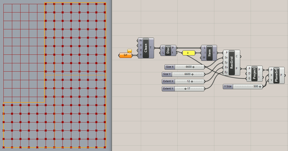
I am aiming to make columns in a limited frame by using grid.
First question, how do you change the starting point of your grid from one corner of the surface to the other corner without rotating the surface? (When I make the grid from the surface I created, it automatically starts from the left top corner. )
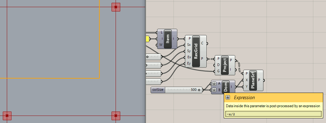
Also how do you generate planesurface using the points as a center of the geometry?
Open question: Is there any other smarter way one can create columns and beams by using grid? What if I want to change the distance between two grids at certain point?
Could you please tell me how I should flip the direction of the grid? Is it not possible to make grasshopper to start the grid from the right end of the corner and to grow toward left top?
It is because I am making it for a renovation project, and the existing buildings are located on the right side of the plane, and we are planning to build new on the left side. So the y axis on theright side is fixed and the left side is rather free.
Thank you so much for posting the edited script again! I was trying by myself to make the same as you did but just could not manage… Many thanks!
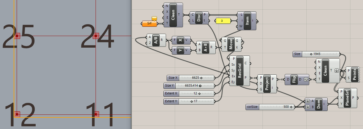
I don’t understand how that makes any difference? Of more concern, I would think, is making sure the columns are all within the perimeter boundary instead of half outside as many are now. This will require care about the building dimensions, column spacing and possibly moving the whole grid of points slightly, by half a column width horizontally and/or vertically. Maybe centering them on the points was not the best idea?
It looks like you are still using 6 as the point index for List Item instead of 3. The code I posted works, use it!
P.S. I still don’t understand your left/right constraints but you could mirror the building perimeter so the short edge is on the right instead of left, get your columns and then mirror everything back as it was.
Rather extreme and a little ridiculous but outside the box, eh? I’m not a fan of working far from the origin and using small units (millimeters or inches) that result in large dimension values.
Here is a way to move the grid reference point (and thereby the whole grid) so the lower left column is aligned with the perimeter. Then I adjusted the RecGrid ‘Sx’ and ‘Sy’ values slightly so the columns are also aligned with the right and top edges of the building perimeter.
OK, maybe this is what you wanted all along? The white group calculates the RecGrid ‘Sx’ and ‘Sy’ values based on the two longest building edge lengths (X and Y dimensions). Changing column size adjusts everything nicely.
Well, what Flip Matrix is doing is a little more complicated than it may seem. To see it, examine the input and output with text panels or by connecting Point List to Project, then to Flip Matrix.
Study that version ‘e’ code and you’ll be there today! It’s not that complicated.