Generating a panelized cover for a boat and cover support frame

Background Intro

Hi all. I’ve been reading topics here on and off for the last 15 months since I started using Rhino (aside from a few weeks of playing with v1.1 25 years ago). In that time I’ve used Rhino to design and build an 8’ x 20’ laser cutter, including modelling parts for 3D printing, and to draw and build a frame to support a winter snow cover for a 26’ boat. I’ve also used OpenNest in Grasshopper to nest frame components on 4’ x 8’ sheets of plywood.

For the last number of months, on and off, I’ve been trying to use Grasshopper to create a template for a panelized fabric cover to cover the combined boat and cover support frame. I’ve made some progress in identifying boundaries and contour lines, but could use some help in making progress in panelizing the surface into developable surfaces that can be cut from 60" (1524mm) rolls of fabric.

I’m trained as a software engineer, with 37 years of programming experience, but mainly with scripting languages (primarily Perl… was once a major contributor to Apache SpamAssassin) and PLC ladder logic, so am not afraid of implementing things in custom components if required.

Goal

Take a mesh of a boat (generated from a 3D scan of a boat) and support frame polysurface objects drawn in Rhino (located on/above the boat mesh) and generate developable panels that enclose the combined boat mesh and support frame polysurface objects to create a winter cover for a boat.

Further Goal Details

  • Allow for some amount of fabric stretch (or overall cover looseness) when determining combined object boundaries to allow for/ignore small protrusions.
  • Protrusions should be identified so that they can be reinforced.
  • Cover should be mostly “tight” around the combined boat and frame objects.
  • Cover only needs to go “down to” the chine of the boat (the edge that transitions from the vertical sides to the bottom of the boat). This edge could be identified manually if needed.
  • Cover should cover/enclose the swim platform on the rear of the boat.
  • Panels can only be about 57" (1448mm) wide plus 3" (75mm) for seem allowances. Narrower panels can be used where needed. As can darts, etc.
  • Panel length can be unlimited, but ideally 17’ (5200mm) or less. A seem along the frame ridge beam would be OK.
  • Identify where panels make large angle changes around the covered (“wrapped”) objects so that reinforcement can be added to the panel.
  • Possibly align vertical panel edges with vertical members of the support frame. Otherwise (and additionally) identify where the panels fall on the vertical members of the support frame so that the panels can be reinforced.

Pictures for Reference

Note: Some of the ground support stands have been trimmed out of the model in subsequent screen shots and the internalized Grasshopper file data.

My Progress So Far

  • Blue curves are fit to some contour 3D-points imported with the boat mesh scan (mainly used to make up for gaps in the 3D scan of the railing towards the front).
  • Red “horizontal” curves (“A-Frame connecting lines”) are identified with some Python3 custom components.
  • Red “vertical” contours wrapping boat mesh and frame are convex hulls (that have been further processed to simplify them).

  • Generated convex hulls of boat mesh and frame on three planes and then generated convex hulls that encompass those convex hulls.

  • Intersection points of the convex hulls to identify potential panel edges.

Grasshopper

This is what my Grasshopper document currently looks like:

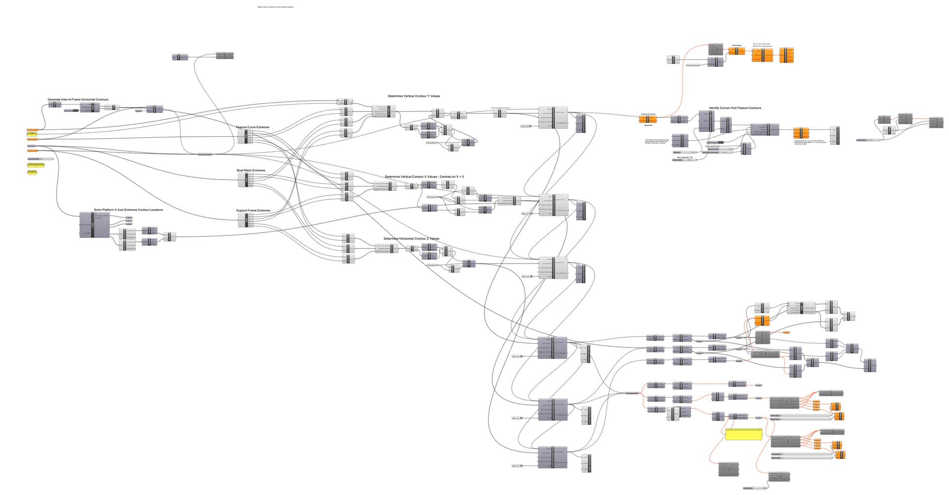
Grasshopper file with inputs internalized: Convex Hull Slices - v2 - Internalized.gh (saved to OneDrive; too big for forum upload) Note: It takes about 43 minutes to run on my computer (11th Gen Core i7-1185G7 with RTX A500 GPU).

I’m Stuck

I’m sort of stuck here. My thought process was to identify the 3D boundaries of the boat mesh and cover frame objects (which I’ve done… sort of a 3D “tight extents” of the object… perhaps more of a “stretch wrap” than a “shrink wrap”) and then try to panelize it… automagically. I’d like to be able to produce cover templates for other boat meshes and cover frames, so looking for a way to do it without a lot of manual steps.

I don’t expect anyone to completely solve the problem for me (but if someone can, perhaps I could compensate them for their time), but could certainly use and would much appreciate some advice and pointers. I’m very open to someone telling me that my approach is totally wrong.

Absent a better (more correct, faster) way to go about it, my next step would probably be to throw a genetic algorithm at it to try to panelize along the convex hull slice intersections.

Thanks for reading all this way. :slight_smile:

4 Likes

I’ve uploaded a revised version of my Grasshopper document with the convex hull contour curve data internalized so that others can avoid the 43 minutes of data generation. This version runs in 60 seconds: Convex Hull Slices - v2 - Internalized Convex Hulls.gh

I’ve also added some labels and a few more custom preview components to make it easier to visualize or turn things on and off.

The Grasshopper document now looks like this:

…and will generate this for you, minus the boat mesh and support frame (although those were internalized, too, in this and the previous Grasshopper files):

I note that I do have a convex hull curve intersection script that detects only intersections that exceed a set number of degrees deviation (“change in direction” of the curves)… it’s the middle right-most script and custom preview.

Any thoughts or ideas on where to go next to panelize the surfaces defined by the convex hull curves / intersections would be appreciated.

Thanks!

Sounds like WAY TOO MANY POINTS :bangbang:

Much better but the file is still too large to post?

This may be a case where it’s better to keep the geometry in a separate Rhino file.

Have you tried shrinkwrap or 3D convex hull?

Moreso a deficiency with the “Convex Hull Contour Curves” collection that does an O(n^2) sort on all of the various contour curves’ points when it combines multiple coplanar convex hulls into single convex hulls, rather than only combining points from only the coplanar convex hulls. It was one of the first things I created while learning how Grasshopper’s data flow works… it needs to be rewritten, but falls in the category of make it work first, then optimize. I didn’t see value in spending my time optimizing things until I knew I had an overall process that produced the results I need (which I still don’t have).

With the 3D scan mesh data still internalized, yes too large to post to the forum, but saved to my public OneDrive. Here’s a Grasshopper document with only the resulting convex hulls:
Convex Hull Slices - v2 - Internalized Convex Hulls Only.gh (568.7 KB)

I have (but it doesn’t appear that I saved those attempts)… they were the first ways I tried to attack this problem, not to say that I did it well. I recall that with shrinkwarp I struggled to produce a tight enough mesh that was smooth/flat enough but didn’t ignore the sharp contour changes of the combined boat and frame. I had better luck with a 3D convex hull of extruded (along Y) 2D convex hull slices (the same XZ convex hull contour curves I have now). The problem I faced with both was panelizing the results into large developable surfaces. I’m happy to revisit either if you have ideas on how to proceed beyond the shrinkwrap or 3D convex hull stage, as I have no idea how to panelize those outputs into about a couple dozen developable panels.

The thinking that delivered me to the result I have now is that if I had a “grid” of points along contour changes, I could try to generate rectangular, trapezoidal, or triangular panels using those points. A shrinkwrap or 3D convex hull would provide similar points, but would be less regularly positioned/aligned, I think.

I don’t have enough experience with Rhino, Grasshopper or its plugins to know what’s the best way to panelize this (the most automagically), so thought I’d check with others here before attempting to write a genetic algorithm to try to fit panels to points (however those points may be determined).

Laser scans always result in very large point files. We routinely work with millions of points. You can reduce the density, but you may lose some information needed at the support points.

Can you use symmetry for the problem? If the boat is perfectly symmetrical in one plane you can reduce the problem by half.

I would approach the problem by creating a 3d model of the boat first. If you plan to do this for a commercial venture your customers will need to supply you something like that. Depending on the quality of your scan data that process can be simple or tedious. Lots of high quality data will make it easy, but you will need to reduce the resulting meshes to resonable surfaces that your can work with. There is specialized software for this.

The problem I’m having isn’t the volume of data or the time it takes…

…my problem is figuring out how to panelize the resultant convex hull contours into a couple or few dozen developable panels. I believe that I’ve produced a reasonably flat, low density point cloud (the contour curve intersections – the images with red contours and red Xs), I “just” need to panelize it now.

Even with software like MPanel, I would still need to identify each of the resultant surfaces first… MPanel would only break them into smaller panels, tension them, add seam allowances and alignment marks.

(post deleted by author)

It is in the sense that many want nothing to do with that many points and that much time (and files that large). Certainly not me :red_exclamation_mark:

1 Like

I’m happy – and eager – to provide anything needed for you or others to help… even just to suggest a workflow.

I’ve provided internalized processed data that loads more or less instantly, and even uploaded a copy (568.7 KB) directly to the forum as you inferred was needed.

Are you inferring that my contour curve → small point cloud approach is totally wrong (if so, that’s fine) and that we need to start over with a super-simplified boat mesh and the polysurface/brep support frame objects?

I’ve literally spent 12 hours assembling what I’ve got and formulating this post trying to be respectful of your and everyone else’s time. I want to make it easy (or at least as quick and easy as possible) for anyone to help. I just don’t know what it is that you’d like. I’ve only heard that I’ve worked too hard/long to get to the processed data stage I’m at… not whether the processed data is useless and that I need to start over.

I downloaded the first file you shared and it does not contain all inputs.

The warnings appeared (not unexpectedly) after I trimmed some of the boat mesh objects (and I guess part of the support frame)… but had continued to work. I think when I selected “internalize” on those inputs that it failed to internalize any of the input collections that had the warning.

I can reselect the inputs and try internalizing them again if you’re wanting to work with the source data.

Thanks!

Now I downloaded the last file you shared…

Perhaps I should have just trimmed that out. As the other label says… I was just experimenting with trying to mesh the intersecting points. That stuff is disabled.

The stuff above that, that is enabled, is what I’ve been working on and providing screen shots of.

The result of that script… What should this be useful for?

Why don’t you use the native 3D convex hull component?

What’s keeping you from modeling simple NURBS on top of the scan data?

Or even just a simple quad mesh model?

Unless I’m missing something, there is no automated Rhino process to rebuild a low poly mesh from scan data…

Also 13’000 points is not a lot by any means.

What are your system specs? Can you run the command _SystemInfo and post the result?

Useful for approximately nothing. I had started to draw meshes between the intersecting points to try and see if it would be a way that I could create panels (by expanding those meshes across more points, allowing for some deviation from the mesh’s plane). I’ve been flailing around for months on and off trying to solve this.

I’ve struggled to understand how I would go about panelizing the native 3D convex hull; along with how I may reduce the number of panels (and get them more “strip”-like, than “quilt”-like). If this is the route I should be heading down, I can spend more time trying to research and understand this. So far I haven’t turned up any discussions on how to panelize a 3D convex hull in a way similar to what I need in my searches.

A combination of not knowing workable ways to approach this to get to developable fabric panel “strips” at a low enough panel count that you could actually sew it together and have it not look like a hideous quilt; and needing to combine the frame with the scan data (I guess I could covert the frame objects to a similar mesh?).

I didn’t think it was…

11th Gen Core i7-1185G7 with RTX A500 GPU, 16GB RAM, 1TB SSD.

Rhino 8 SR16 2025-2-11 (Rhino 8, 8.16.25042.13001, Git hash:master @ d0f731de6fe2c5fdcad78ad80faf154307815f18)
License type: Educational, build 2025-02-11
License details: Cloud Zoo

Windows 10 (10.0.19045 SR0.0) or greater (Physical RAM: 16GB)
.NET 7.0.0

Computer platform: LAPTOP - Plugged in [100% battery remaining]

Hybrid graphics configuration.
Primary display: Intel(R) Iris(R) Xe Graphics (Intel) Memory: 2GB, Driver date: 11-26-2024 (M-D-Y).
> Integrated graphics device with 4 adapter port(s)
- Secondary monitor is laptop’s integrated screen or built-in port
- Windows Main Display attached to adapter port #1
- Secondary monitor attached to adapter port #2
Primary OpenGL: NVIDIA RTX A500 Embedded GPU (NVidia) Memory: 4GB, Driver date: 10-15-2023 (M-D-Y). OpenGL Ver: 4.6.0 NVIDIA 545.86
> Integrated accelerated graphics device (shares primary device ports)
- Video pass-through to primary display device

OpenGL Settings
Safe mode: Off
Use accelerated hardware modes: On
GPU Tessellation is: On
Redraw scene when viewports are exposed: On
Graphics level being used: OpenGL 4.6 (primary GPU’s maximum)

Anti-alias mode: 4x
Mip Map Filtering: Linear
Anisotropic Filtering Mode: High

Vendor Name: NVIDIA Corporation
Render version: 4.6
Shading Language: 4.60 NVIDIA
Driver Date: 10-15-2023
Driver Version: 31.0.15.4586
Maximum Texture size: 32768 x 32768
Z-Buffer depth: 24 bits
Maximum Viewport size: 32768 x 32768
Total Video Memory: 4 GB

Rhino plugins that do not ship with Rhino
C:\Program Files\Rhino 8\Plug-ins\MeliarComR8.dll “MeliarComR” 8.0.8515.25198
C:\Program Files\ADA 3D\Mesh2Surface for Rhino 6\m2s_for_Rhino.rhp “MESH2SURFACE”

Rhino plugins that ship with Rhino
C:\Program Files\Rhino 8\Plug-ins\Commands.rhp “Commands” 8.16.25042.13001
C:\Program Files\Rhino 8\Plug-ins\rdk.rhp “Renderer Development Kit”
C:\Program Files\Rhino 8\Plug-ins\RhinoRenderCycles.rhp “Rhino Render” 8.16.25042.13001
C:\Program Files\Rhino 8\Plug-ins\rdk_etoui.rhp “RDK_EtoUI” 8.16.25042.13001
C:\Users\doshea.DOSTECH\AppData\Roaming\McNeel\Rhinoceros\packages\8.0\PanelingTools\2024.8.20.677\PanelingTools.rhp “PanelingTools”
C:\Program Files\Rhino 8\Plug-ins\NamedSnapshots.rhp “Snapshots”
C:\Program Files\Rhino 8\Plug-ins\MeshCommands.rhp “MeshCommands” 8.16.25042.13001
C:\Program Files\Rhino 8\Plug-ins\RhinoCycles.rhp “RhinoCycles” 8.16.25042.13001
C:\Program Files\Rhino 8\Plug-ins\Toolbars\Toolbars.rhp “Toolbars” 8.16.25042.13001
C:\Program Files\Rhino 8\Plug-ins\3dxrhino.rhp “3Dconnexion 3D Mouse”
C:\Program Files\Rhino 8\Plug-ins\Displacement.rhp “Displacement”
C:\Program Files\Rhino 8\Plug-ins\SectionTools.rhp “SectionTools”

Thank you for taking the time to look at this. :slight_smile:

I’m not a specialist for hardware but I think you may want to update this driver

My understanding is that Grasshopper is all/mostly CPU bound, but I’ll see what I can find for a driver update… the RTX A500 is in an external “Pocket AI” enclosure. Thanks.

I think once you have a decent mesh you will need to split that into logial areas that can be flattened like one does in other industries. Maybe Martin can generalize this, but I don’t imagine boats are similar enough for a single script to work well.

I assumed far more points in your point cloud based on the 43min process time. Our lidar scanner collects 15,000points per second and newer versions collect far more.

For revsere engineering I am more familiar with tools like Peel Scanner. I have never seen someone use one for this size.

1 Like

There are dedicated tools to unroll strips and Kangaroo can be helpful. This is from an example here somewhere in the forum:


If you stick to quads, you can unroll strips with Kangaroo.

I have no experience with ship covers but I’ve worked on doubly curved membranes like this:


1 Like