I am trying to flow a series of “obrounds” along a surface and the resulting objects vary in size for some reason, which I cannot seem to crack. My workflow:
Smash surface (surface is a revolved curve)
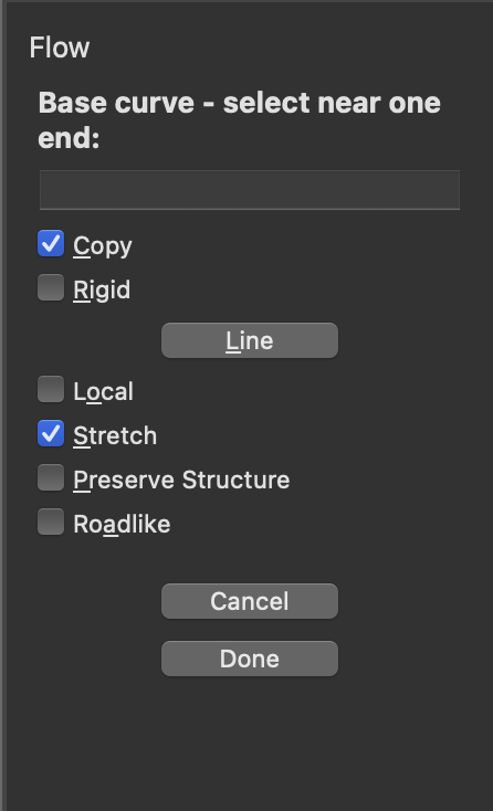
Flow “obrounds” using linear curve to curve offset from smashed surface. Settings are Copy and Stretch.
FlowAlongSurface the resulting “obrounds” from the smashed surface to the revolved surface. Settings are Copy and Auto Adjust.
For some reason, the “obrounds” vary in size as follows: same size at N, E, S, W, same different size at NE, SE, SW, NW. I’ve tried checking and unchecking Auto Adjust in FlowAlongSrf, along with every other combination of settings I can think of. The revolved surface seems to be aligned and perfectly round, as check also by extracting iso curves.
Hoping someone either A, can identify where I am going wrong, or B, has be better workflow altogether. I am not concerned about the “obrounds” themselves getting slightly distorted, but I would like them to be the same size.
Well, I kept trying and arrived at may a “good enough” solution. I still don’t feel I can control this well, but the variance now is negligible. I adjusted the base objects for the Flow operation so none of the “obrounds” are split.
The odd thing is that using the above-mentioned workflow, I achieve “obrounds” of identical size on a revolve-surface with a slightly different profile curve. Not sure how.
So, now, my purpose here is to understand a repeatable, controllable workflow. I would appreciate any insight. Thanks!
rebuilding the revolved surface seems to help. I’ve used 32x4 points with 3/3 degrees. To have better control of the positioning from the smashed surface to the revolved surface you might check surface domains too. The revoved and smashed surface have domains like:
U = 0 to 178.442
V = -28.7899 to -18.8607
use _Reparameterize _Automatic to reset the srf domains to something reasonable.