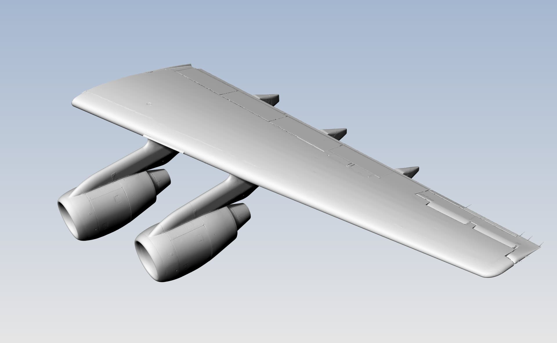
I’m working on an evolution of workflow when dealing with laser scanned data of aircraft wings. The goal is to create the “jig” version of the wing assembly - ie remove the droop in the wing caused by its own weight when on the ground. In the past I’ve done all the modeling on the “as scanned” data, and then adjusted it after the fact. I had a realization that I might be able to adjust the laser scanned data itself first, thus saving a lot of work. I’ve created two very simple surfaces that represent the tops of the wing spars - since those are what need to be flat - one representing the current droop, and one for the target that’s flat. This is working SHOCKINGLY well, except for one weird display issue. Here is my raw, as scanned data:
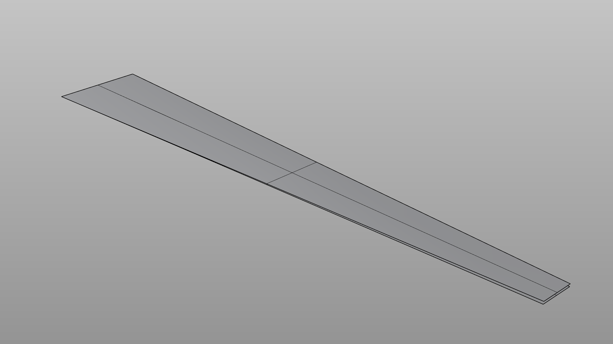
My base and target surfaces:
The original and flowed meshes:

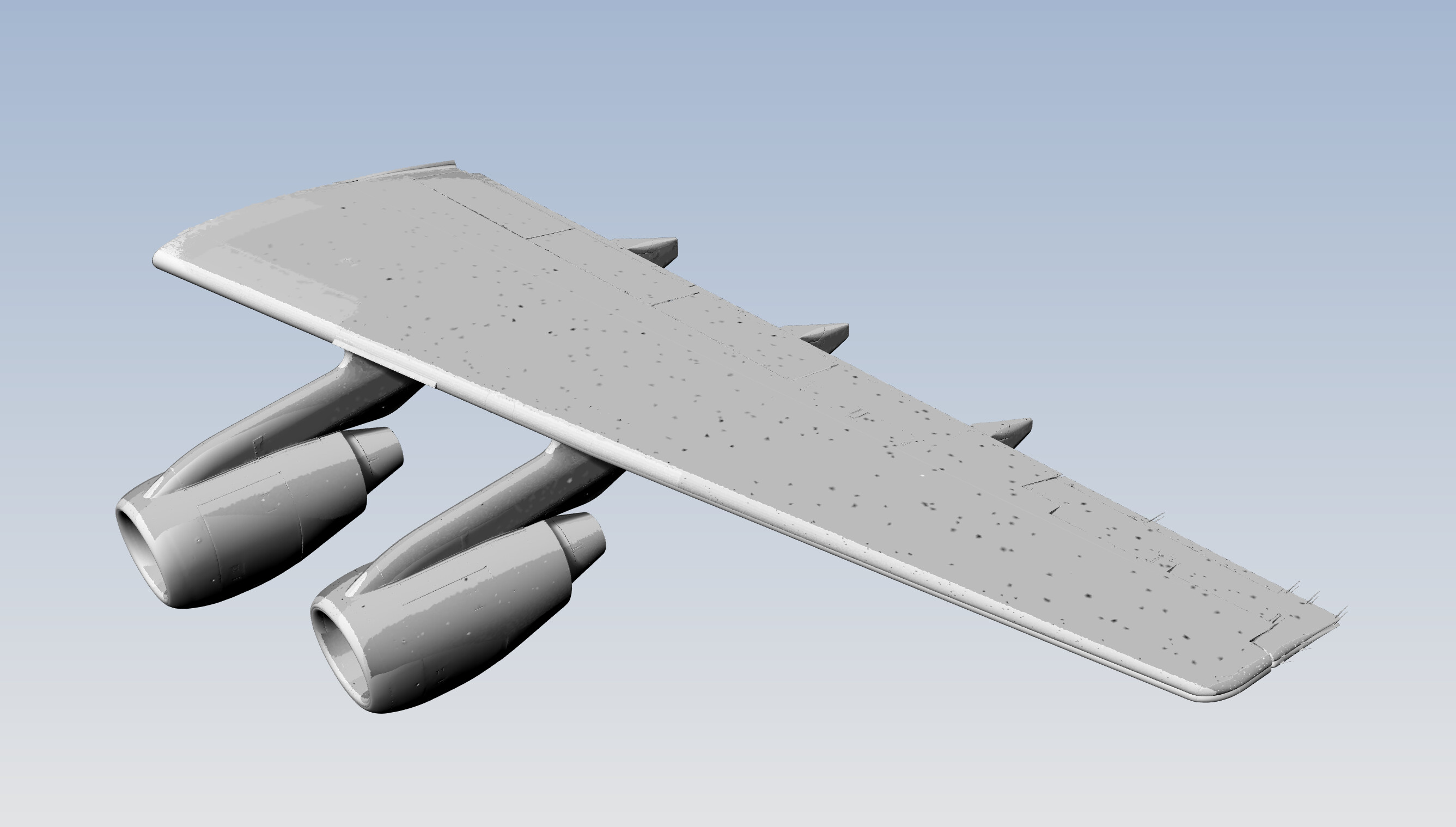

On the one hand, this seems to be working exceedingly well! On the other - I’m getting these odd spots and areas where the “color” of the mesh changes. Any idea how to fix this, or keep it from happening?
-Sky