
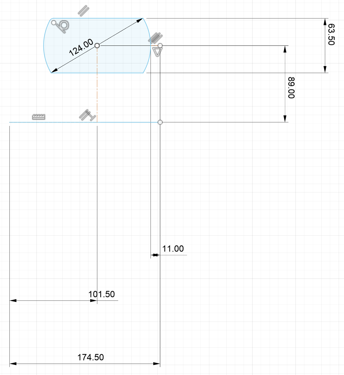
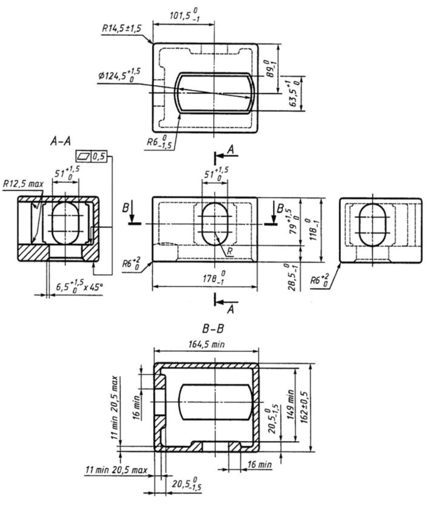
Following the top view of the first drawing, the overall length turns out as 174.5 mm, but the front view of the bottom drawing says it is 178 mm, which is correct?
The middle drawing was made using the nominal dimensions of the top drawing, should the median value of the bilateral tolerance have been added to the nominal value?
The top drawing actually says the length is not less than 175.5. The bottom drawing shows it as 178 or no more than 1 less than that.
The two dimensions are compatible, but you should probably use the bottom set as they are expressed more precisely. Don’t try to mix and match dimensions from the two drawings.
Alternatively, ask the product owner to explain the reason for having two different systems of dimensions and ask them to specify which dimensions to use for your purpose.
HTH
Jeremy
1 Like
Thank you, these are ISO standards with the top one being the latest one, and I am not sure why they made it that way.
Also, if I understand correctly, it is a bad habit to include extra dimensions as it needs to show design intent. So how would one know where to start from if they were to create such part? Especially if the latest ISO standard is the top drawing, which overrides the bottom one.
Edit: The bottom drawing also states the length is a minimum of 164.5 mm while also stating that it is 178 mm or no less than 1 mm of that. Which confuses me even more.
That’s the problem with bad drawings…
1 Like
I think I found the issue, the top and bottom drawings are not the same object.