I created a SubD Radial Symmetry example in Grasshopper after looking at this topic.
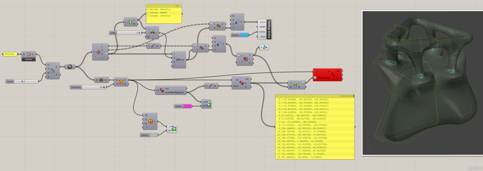
The goal is to be able to work a a single segment, rotate this segment and weld everything into one SubD. Unfortunately after welding and aligning the vertices, all edges are smooth and creases are lost. There is an option to keep creases at Mesh Edges, but it’s impossible to distinguish between interior edges and naked edges. The solution is to weld everything and unweld based on edge indeces.
The problem right now is that the unweld script doesn’t work anymore. For whatever reason?
The initial segment has three edge tags:
smooth, interior
crease, naked
crease, interior
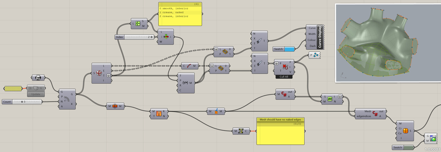
Let’s say I want to keep interior naked edges creased. The edges can be filtered and unwelded.
Some time ago in an old topic I had a similar problem, but the script from a year ago does not work anymore.
private void RunScript(Mesh M, List<int> edgeindeces, ref object A)
  {
    MyClass edge = new MyClass();
    List<int> edgeindeces = new List<int>();
    foreach (var val in edge)
    {
      A = Rhino.Geometry.Mesh.UnweldEdge(edge, false);
    }
  }
Did you create a class called MyClass? You are trying to create an object of this class and it seems not to exist.
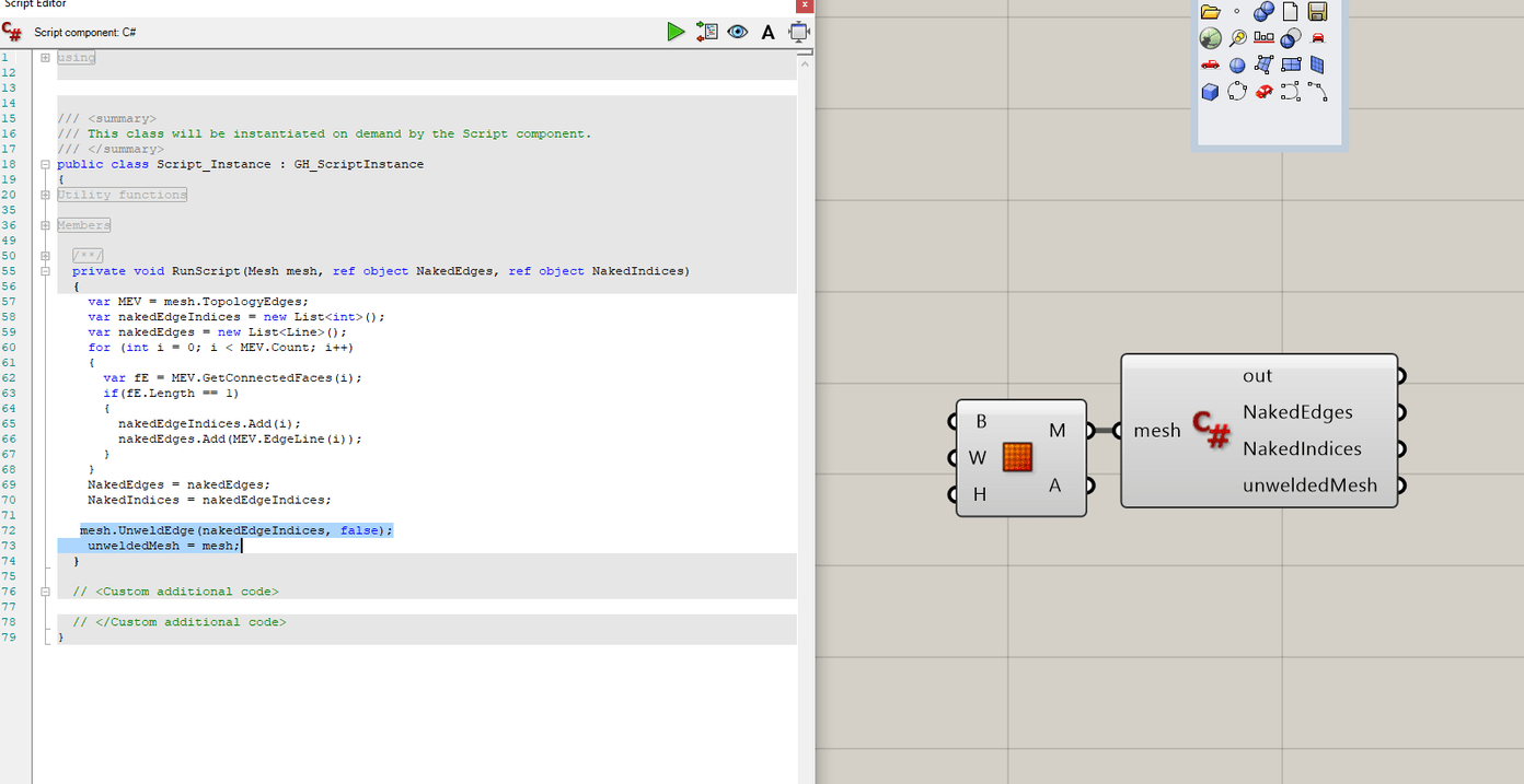
If you want the naked edges you can do something like this:
 var MEV = mesh.TopologyEdges;
    var nakedEdgeIndices = new List<int>();
    var nakedEdges = new List<Line>();
    for (int i = 0; i < MEV.Count; i++)
    {
      var fE = MEV.GetConnectedFaces(i);
      if(fE.Length == 1)
      {
        nakedEdgeIndices.Add(i);
        nakedEdges.Add(MEV.EdgeLine(i));
      }
    }
    NakedEdges = nakedEdges;
    NakedIndices = nakedEdgeIndices;
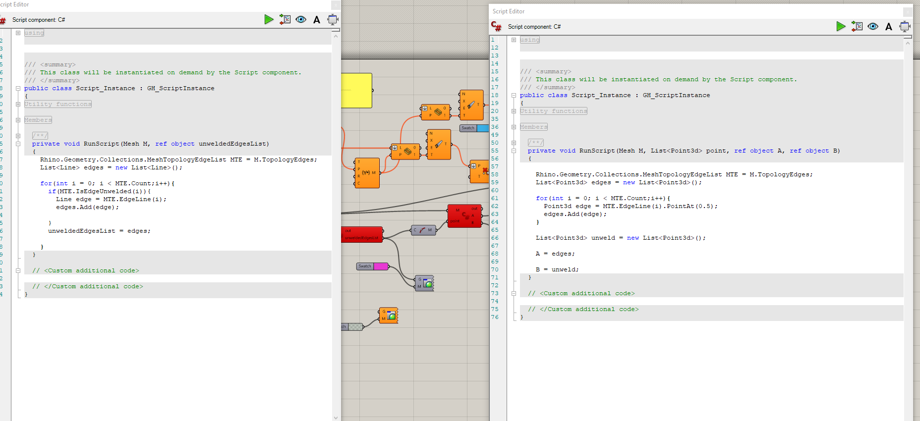
I have not Rhino 7 installed to further try stuff, but there is some strange things going on in the c# scripts:
Besides the really confusing naming it is redundant:
Hi Martin
I am testing your definition.
Works very well, but there are small issues.
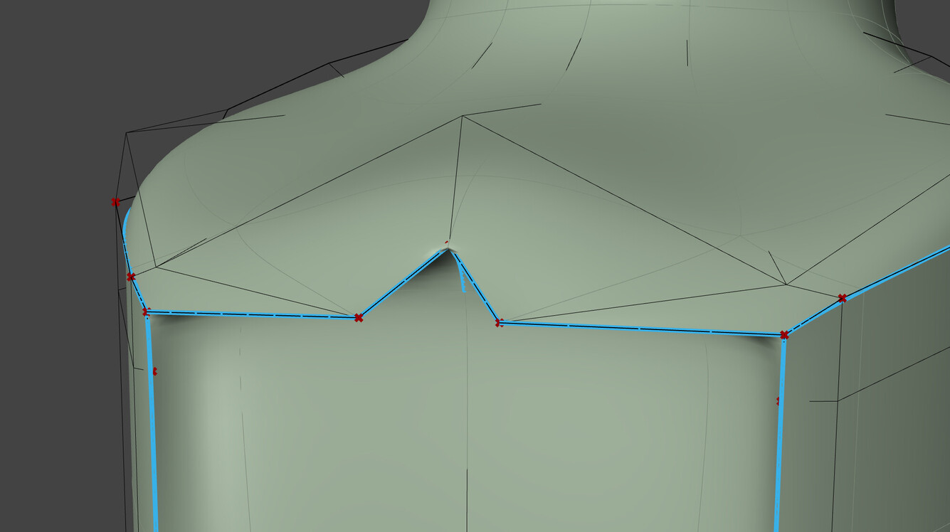
I cannot sort some folds where there is a dot with a crease at the corners.
In the original model, the point is a sharp crease, but the definition creates a smooth crease. Could you work it out please?
I attach your definition with creases sorted for my model
There is also a general question about the Grasshopper.
A preview of the resulting geometry is always shown in the DisplayMode by default. I mean light scheme.
For comfortable modeling and familiar perception in the process of work, I want to get a preview with the settings of my display mode. For example my Shaded or my Rendered. How to do it?
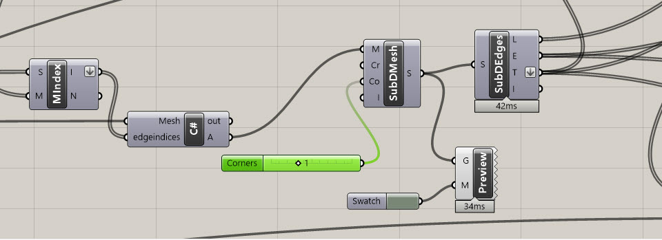
There’s the corner setting on the ‘SubDFromMesh’ component which should be set to ‘At Mesh Corners’ but other than that I don’t know what the problem is. Somehow it depends on the choice of creased edges. I’m usually trying to avoid sharpe edges on SubD geometry unless it is really required. Instead I would add another loop or ring or bevel an edge.
This is a multicomponent model Subd + Nurbs
In the empty cavity I will inscribe the geometry from planes that have sharp corners, so I need a sharp corner of Subd. Well, among other things the inconsistency of the obtained geometry from GH makes me confused.
I have set a new component for corners, change values but nothing happens. I can’t understand why.
@martinsiegrist I do not have rights!
Does it look strange or so unfriendly?
Thanks a lot anyway dear Martin!
Not finished but our work will benefit many other users.
Radial symmetry has not yet been realized.
Regarding your problem of sharp edges… T-Splines had an option to match a curve or surface and add a refinement for closer matching. In case of your star shape, the edge is still not perfectly pointy