I reported this about a year ago and had hoped it might be fixed by now. It adds so much work to my workflow so am hoping some attention can be given.
I set the direction to ‘Free’ and then to ‘V’.
Then I set a number to extrude to (say 2)…some of the values are right but many times the values are ‘what-ever Rhino wants’ and it means having to go through and fix every one by hand. The example shown is a ‘good’ result. Many times it is very bad.
I know there will be crossed polys regardless…that I can deal with.
Please give this some attention. I use this tool all the time.
1 Like
Perhaps you’d like to include a link to your earlier post and share your example .3dm file?
I have no idea where that post is…someone from McNeel had acknowledged the problem when I posted.
While I am on bugs…please fix the ‘right mouse click on the Edge Select Tool’ to turn it off. This has never worked and has already been reported.
can you clarify a bit on that… can you give a file and steps to repeat?
can you clarify this a bit?
can you give steps by steps on how to reproduce this problem? I’m happy to write it up or rebump the original request.
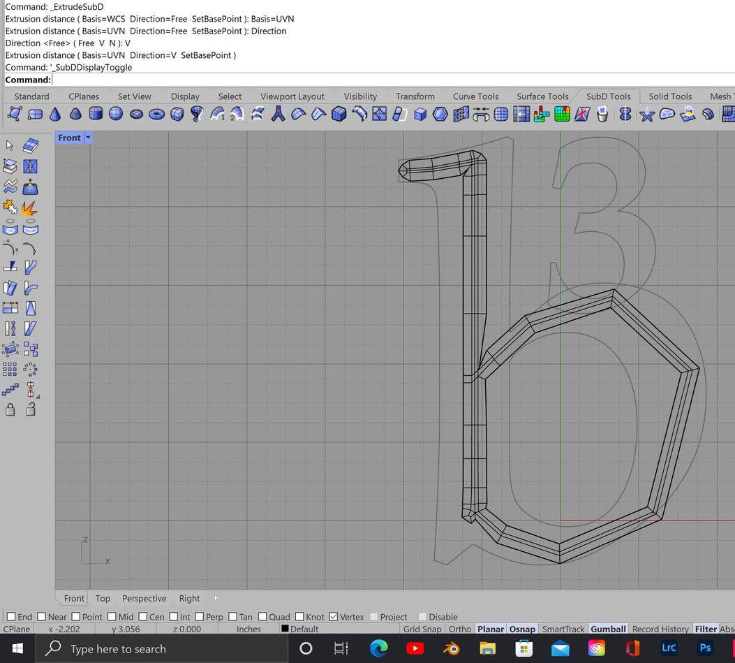
Here’s a file. Very simple to duplicate as it always happens on every project I’ve done.
Select all of the outside edges. Hit Extrude SubD. Change dialog to ‘Free’. Then change to ‘V’. In this case type in .15. Then do the inside edges if needed.
It’s a great tool. Modo has this but it is called a bevel tool (the bevel tool does much more) which does this function if outside edges are selected.
Extrude.3dm (322.1 KB)
Extrude.3dm (322.1 KB)
Same file uploaded twice.
what exactly are you trying to do? Are you trying to add like a ribbon to the outside of the model?
Yes, I thought it was very straightforward what I am attempting to do. Add a ribbon around the whole model at the definite width. In Modo it is extremely easy to do.
Yes, I am referring to UVN. If you look at the first screen grab I uploaded it shows what I did in the dialog box.
Why would I do this in the perspective view when I am trying to get a ring of polys around the outside of the form a specific thickness?
If there is a better way to do this please tell me… but I spent many posts with someone at McNeel over a year ago and this was the only solution offered. I asked for a tool to mimic Modo’s Bevel tool. If you don’t have Modo as an example of an app doing SubD’s right McNeel should spend a few dollars and get it.
we don’t reference other software for the very obvious patent and IP infringement issues.
I see the workflow now and it’s working as expected- ignore my comment about perspective… I was doing it wrong based on your steps.
so the complaint is if you enter a unit value, the unit value is not consistent to the rest of the model? (which is what I am seeing here)
this was my result after I entered .15

If I type in 1" I want the ribbon to be 1" all the way around. It changes arbitrarily as it ‘extrudes’ different edges. Is that clear?
Also…why is it ‘rounding’ as it goes around corners?
got it- I’ll write this up.
1 Like
Thanks for looking at this. I know it had been filed over a year ago and I had hoped it would have been resolved by now.
Just to recap…and I’m sure it’s understood. I just want to use the Extrude SubD tool to create a ribbon of determined consistent width on the outside of selected edges. Very similar to the ‘Offset Curve’ tool. The offset does not get thicker nor thinner as it calculates the curve.
I know there will be overlapping and crossing polys if the ‘ribbon’ is too wide. Those are easy to fix as opposed to fixing the whole ribbon width. It would be wonderful to have an upgrade to the tool to calculate overlapping polys and merge them so the ribbon width continues regardless of problem corners, etc. But, have this as a toggle option as many times it’s important to maintain the integrity of the poly edge count.
By the way, I really appreciate the YouTube video you did on changing the buttons in the pop-up pallet from the middle mouse click.
This is the one I am referring to.

And while I have your ear ![]() I would absolutely upgrade to V8 right now if only this function could be added to the SubDs. Nothing else. Just this function.
I would absolutely upgrade to V8 right now if only this function could be added to the SubDs. Nothing else. Just this function.
Please, please make the SubD Crease tool have a variable amount control (rather than on and off) and then, when and if, the SubD is converted to Nurbs, the crease amount is calculated in the conversion.
This would make using SubDs far, far easier to master…or just have more fun with :-).
1 Like
yep, understood. Since I filed it again, it’ll pop up on my list of things to chase. I tend to be a little more persistent (annoying) about pushing this stuff than others.
glad you liked the pop up video, always nice to hear that folks find that stuff useful.
1 Like
Understood-
Variable creases are high on our dev wish list but there are some high technical hurdles to cross to get them to be compatible with nurbs (which is the main difference between rhino subd and others) I’m not a math guy, but the folks here tell me it’s not an easy get. That said IMO that is a heavy lift worth doing.
2 Likes
Also, just to ensure it didn’t get lost is the ‘Right Click’ on the ‘Edge Select’ tool icon to go back to general selection capability. Just like the Right Click on vents and faces do.
Yes, the variable crease to curbs would be an amazing accomplishment! But if that can’t happen then at least variable crease within the SubD domain.
The pop up video…actually, all of your videos are great! But that one I found the most useful currently. Saving much mouse moving.