I created gyroid structure in grasshopper. Everything is ok and I can export this mesh to STL format for 3D print… But I need do some FEM analyses in ansys. So I need to export this mesh / STL file to igs format. But I still got error: IGES export type default does not support polygon meshes.
So is the way how to export my gyroid structure to igs format ? (Strucure have about 4 000 000 polygons)
There are two main groups of geometry in CAD. Polygons=“meshes” and Splines-based=“surfaces” shapes. Surfaces represent a shape by parametric equations ( Nurbs, Béziers, Hermite, Lagrange, Newton … ). Having a true mathematical representation is beneficial, even required for many engineering tasks.
Iges and step are typical data formats for surface data.
Usually modelling with meshes is much easy and often enough for things like 3d printing. That’s why you see a lot of these in Grasshopper. Using geometry from the surface tab in Grasshopper is much more demanding.
If you have used a sub-d mesh approach and Rhino 7, you can try to translate this into sub-d surfaces and from there to Nurbs surfaces. But usually a surface contains more information as a polygon and as a consequence cannot be just converted. It’s like going from a pixel image to a vector image…
Yes, I understand this. But is the way how to get igs format from this mesh created in Grasshopper ? I know that some CAD have reverse enginering to do this… But 4 milions polygons are a lot of. And My 16GB ram not enought… Because I already tried it in Freecad. But pgoram still crashed… Also I tried reduce mesh… But this did not help…
Or is the other way how to created igs format (not mesh or STL) ? Or is the way how to do analyses in Ansys with stl format ?
Iges cannot deal with meshes, so you need to have a valid shape of surfaces. You are right, there is so called “reverse-engineering” software to make Nurbs-surfaces out of a mesh. But this is a controversial thing. Usually, if they succeed the surface data is garbage, but it may work very well for some cases. Hart to tell.
If you go for this reverse engineering approach, a so-called remeshing is a good decision. @DanielPiker has a good solution to this for Grasshopper. If he is not replying search this forum for his remeshing posts…
I don’t know Ansys, but at some point Ansys creates a mesh for FEM purposes, I guess. The reason why it demands surface data, is probably due to the fact, that surface data allows you to create this analysis mesh dynamically, since a surface model allows you to create any point on the shape.
The easiest solution I guess is to create your shape in surface representation from beginning on. Sub-D surface, as the new technology of Rhino7, will help you with your gyroid shape
Thank for your answer I found Daniel Piker solution but this is remeshing… So this did not help me with this because I have mesh and I want just to export this mesh to igs. I tried remesh my structure and then export as igs format but also did not work…
I am not sure that Sub-D will help me with this because I am generating structures by equation: Gyroid Minimal Surface (Grasshopper Tutorial) - YouTube (I have also other structures and I do not know how to create it manually)… So everything I need is only export to igs
I mean as a step before you use “reverse-engineering” software, it may be a good idea to improve the mesh density before doing it. As you said, your data is probaly very large.
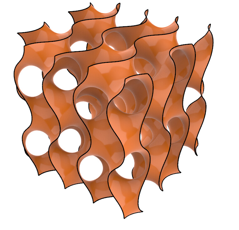
The gyroid is a favourite surface of mine and I’ve played with it a lot over the years.
Generating it as a level set mesh like in the tutorial you link is very heavy though.
I agree remeshing would be of limited use here if you’re ultimately after a surface - you could improve the triangle quality compared to the isosurface, but you’d still have a mesh with lots of triangles.
For other triply periodic minimal surfaces, like the Schwarz P and D surfaces, there are well known quad representations which can be used as a basis for a subdivision surface.
The gyroid is trickier though as it doesn’t have any straight lines or reflectional symmetry (which I think is also one of the things that make it such a fascinating object).
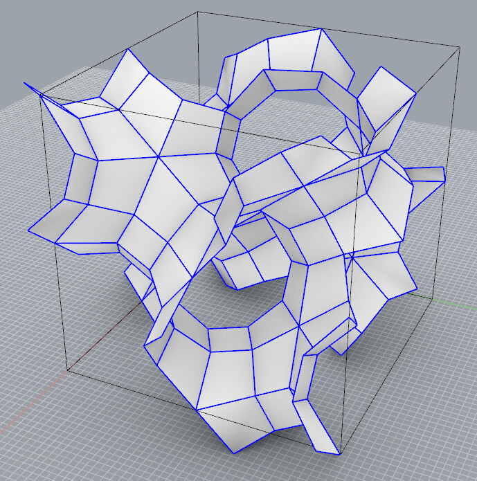
I actually discovered a few years ago a discretization of the gyroid into only 2 shapes of planar quad, which as far as I could find has never been documented before.
(Note that creating a simple planar quad form like this is not an easy or automated process - it took me years to find this one)
gyroidplanarquadunit.3dm (63.8 KB)
This can be used as the basis for a SubD version of the surface
If you array this unit with the box shown as the unit cell, join it (and run AlignVertices to make sure all vertices are connected), you can then convert it into a SubD to get a file which is lightweight and smooth.
“Only” is the wrong term here. You cannot participate on an exhibition showing oil paintings with photographs. You can make a photo out of an oil painting, but the otherway around is much more difficult.
By the way, there is a “dumb” solution which maybe is good enough for you use-case. You can convert any mesh face into a single surface. The command is called _mesh2srf (I believe)
Hi Daniel, thank you for your sharing. do you have any idea, when i get some gyroid array with this subD, how can i change the constat value from the Gyroid formula, becaust i want to do some research to gyroid with the different offsets.