It’s been whole 5 years since I started this topic, but I will remind the Rhino developers once again that using a dual tolerance setting for Trim/Split/Project has a real impact on accuracy in Rhino and the majority of users will benefit and notice it while they work with the program. Here is another example that shows the difference that a running the aforementioned 3 tools internally at a higher precision will deliver much superior quality.
maybe after the split fails (internally) Rhino could ask of it should increase the tolerance? like join does when you use the brutal version of join for curves, for those who dont know it calling join first then selecting the 2 joining points in a sequence letting us know how far apart etc.
@Rhino_Bulgaria In that video, I fail to see what the issue is. As far as I can tell things are well within your modeling tolerance? Also you are building the fillet with 10x tighter tolerance, so of course that will give you a more accurate fit to the surface.
Do you have a model where things fail to give you a result within tolerance at the tolerance you are modeling at?
Allow me to add some confusion to this discussion…
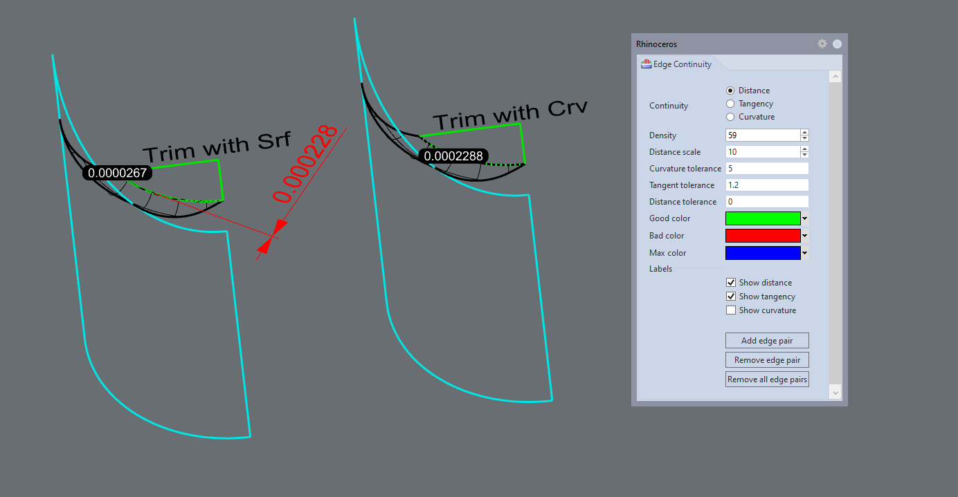
The real issue, as far as I can see, is how Rhino reports Edge Continuity seems to work depending on the method used to create the edges.
It has always seemed to me that whenever you trim with a fillet (as in the video) Rhino always creates Pollyanna numbers for edge tolerance. What I mean is that how can the edge of the fillet get any closer to the surface that it is on just because the user changed the tolerance before trimming? And even more wondrous is how can the tangent continuity improve tenfold by the user changing the tolerance?
I can see how the positional tolerance can improve depending on the user tolerance when both surfaces intersect fully. In theory, if both surfaces carry on past the intersection then you can refine the intersection curve be as accurate as you want. But when one of the surfaces is a fillet that surface was created with an edge a fixed distance from another surface. You can’t make that edge any closer or farther from the surface by running the split command. How does changing the tolerance make the distance of the edge to the surface any different? How does changing the tolerance improve the tangent continuity?
edit:
Oh wait. I just answered my questions by watching the video again. The tolerance was changed before making the fillet. So yes, one would expect the edge to be more accurate. It also will have a denser knot structure.
Yes, I’m sorry I missed the fact that Bobi changed the tolerance before making the fillet not after, so his splitting was not using the same fillet with a different tolerance.
However, That doesn’t change the point I was making. What I was saying is the numbers you see EdgeContinuity reporting in the video are bogus. The actual distance that fillet edge is to the green surface being trimmed is much greater than EdgeContinuity is reporting.
This inaccuracy in edge tolerance creation occurs when trimming is done by using the fillet surface as the cutter. If the user does the trim or split with the edge curve then EdgeContinuity seems to report a result which accurately reflects the actual distance that edge is from the surface.
In the above picture the Red dimension was created by pulling the edge of the black fillet to the green surface and then adding the dimension at the point where CrvDeviation reported the maximum.
Notice when trimming with the edge curve you get a set of edges that accurately reflect the best edge possible for both surfaces.
When trimming with the surface the edge tolerance becomes a fictional number that paints a more rosy picture of the accuracy of the two edges than actually exists.
Hi, @Gijs ! I think that my first video in this topic is a pretty good example that shows the advantage of using 10x or 100x greater precision for certain operations that directly impact the general precision of the subsequent surfacing tools (even of the latter are using the default file tolerance):
There is a test file in another post in this thread, too:
Also, it must be taken into consideration that the file tolerance often times produces possibility to future errors. For example, surface A and surface B are both trimmed with 0,01 mm accuracy, there is the risk of not being able to join them together, because surface A may be slightly off towards one direction, while surface B may be slightly off towards the opposite direction, resulting in up to 0,02 mm common deviation.
Join command allows deviation of 2 x absolute tolerance to allow for situations where the deviations of the edges are each within the absulute tolerance but in opposite directions.
That’s a good example of a tool that takes advantage of an own tolerance setting which is different than the general one. The custom tolerance setting found in “Match surface” is yet another clear example that it’s totally possible for a 10x or 100x more strict tolerance for “Trim”, “Split” and “Project” to be implemented by the developers, should they wish to do so.
I would argue that it was an appropriate example of a single tolerance setting.
Think about simple numbers and a model tolerance of 0.01.
Is 0.00 the same as 0.00? Obviously.
Is 0.006 the same as 0.00? Within tolerance, yes.
Is -0.006 the same as 0.00? Within tolerance, yes.
So is 0.006 in the same location on a number line as -0.006 in a strict context such as whether two parts ending at those points, coming from opposite directions, connect to each other? There are good reasons to say ‘yes’ with that single tolerance given that we already agreed that they are both approximately at the zero point.
Hi @pascal , your macro is a proof that 100x more precise “Trim”, “Split” and “Project” is the only solution to many cases where the current implementation of those 3 tools often fail.
Try this 3d model (provided by me at the beginning of this thread) with the default “Trim” tool, then give it another try with your macro with the following settings for the absolute tolerance (100 times more precise than the file tolerance):
You will notice that even if you set a tolerance of 0,0001 mm, the “Trim” tool will still fail, despite that the curve used as a trim object is 0,0082680 millimeters away from the edge of the surface to be trimmed.
The same goes for the angle tolerance, as well. In my opinion, it also must be 100x more precise while using “Trim”, “Split” and “Project”. Only then Rhino is much more accurate and produces far less errors while using those tools.
This could be optional, but it really helps in some tricky situation. It’s nice that at least a macro like yours could be used as a workaround.
I’m very puzzled that trim works at any tolerance. If you go to a left view and zoom in very close near the middle of that curve and then untrim the surface you will see that the curve you are trimming with is about .01mm outside the natural boundary of the surface if the curve is projected to the surface and about .02mm outside the surface if the curve is pulled to the surface. Of course ,you have to first extend the surface to see where the curve would land when it is pulled to the surface.
If the surface had been big enough to begin with (say .1mm bigger on all 4 sides), I suspect no trimming or joining problems would have emerged and more important the trimming at .01mm tolerance would be more accurate than trimming at .00001 tolerance.
Also, your surface is loaded up with multiple knots. If you avoid surfaces with stacked knots you will have a lot less problems with trimming and joining. I suspect the surface was made using sweep2 command. This is a bug that users have been complaining about for 25 years. And McNeel won’t even acknowledge it as a bug much less try to fix it.
I had plenty of similar cases even with perfectly clean and simple single-span surfaces. The only solution in these cases is to bump the accuracy 10 or 100 times. Sometimes 10x angle tolerance also helps, but usually leave some inaccuracies when compared to the trimming curve or surface. From my experience, temporarily bumping the absolute tolerance 100x and the angle tolerance 10x is the best combination for achieving perfectly accurate trims. But it would be nice if that option was built-in into the “Trim” tool itself.
I found that the ! _Intersect tool also causes some tiny deviations. It would help a lot if “Split”, “Trim” and “Intersect” all have their own customizable tolerance setting which is apart from the main Absolute tolerance of the file.