Hi all, I’m new to grasshopper and am trying to create a wall via the use of contours which has gaps in-between. The current script works in the Z and X direction, but I want the wall to go into the Y direction as it gives the effect I am looking for. However, something about the Dispatch component doesn’t work as intended when the Y direct is plugged into the script. Although set to false, true to delete one contour leaving the other and deleting the next and leaving the one after the last the outcome is currently not achieved.
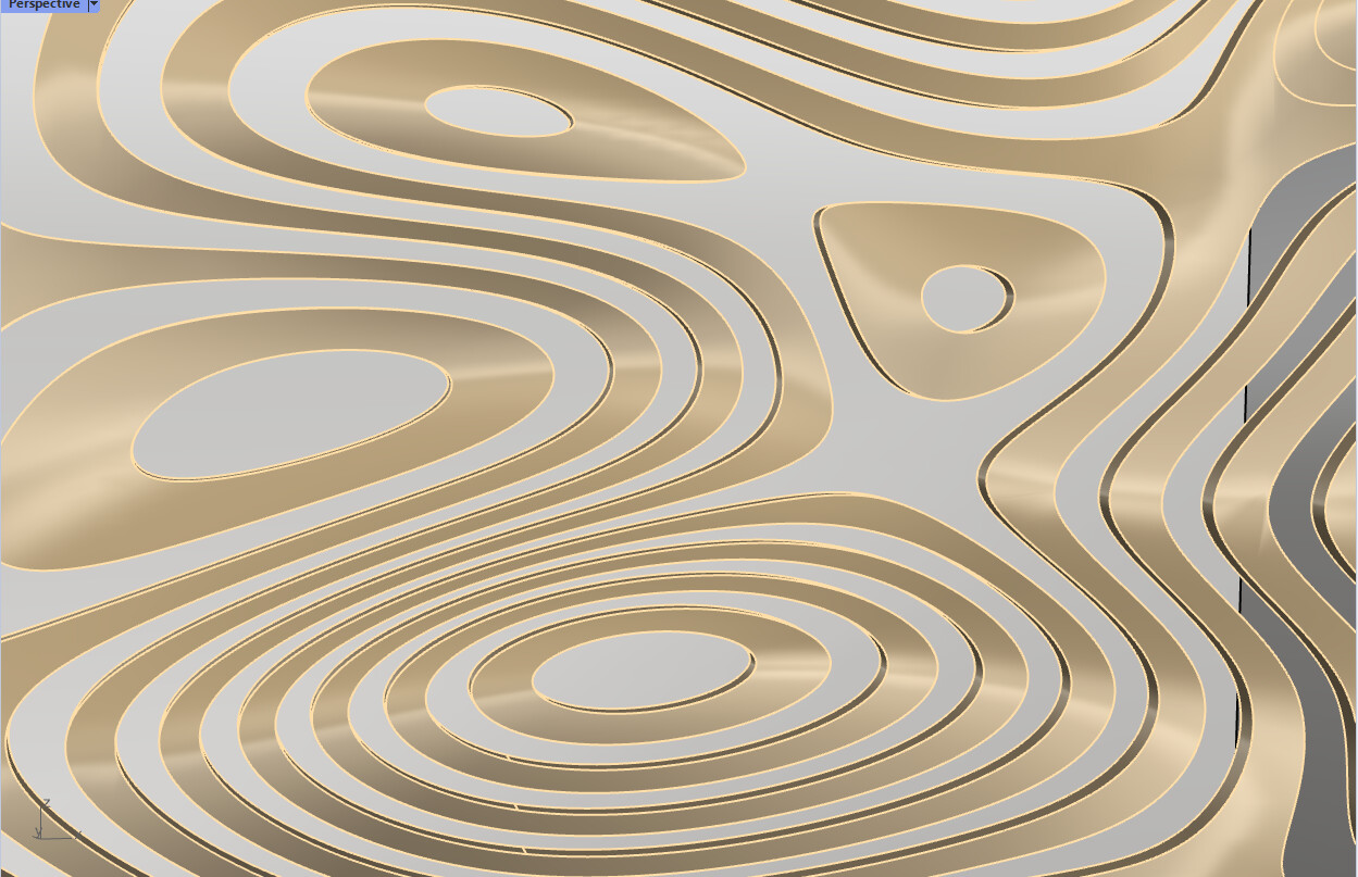
I have two screenshots, one showing the issue and the other is the effect I want to achieve but is going into the Y direction instead of the X direction.
Oof! That file is extremely slow to open… Which image is correct and which is wrong?
Your description is not that clear to me. Still waiting for the file to open! Some solid operations, perhaps? First thing I’ll do is disable the slow parts to examine the code. Had I know, I would have disabled the solver before opening the file.
OK, I’ve waited long enough so will close Rhino and reopen the file with solver disabled.
Rats, I didn’t disable enough components, it’s still locked up. Have you got a grafting error causing thousands of geometry bits?
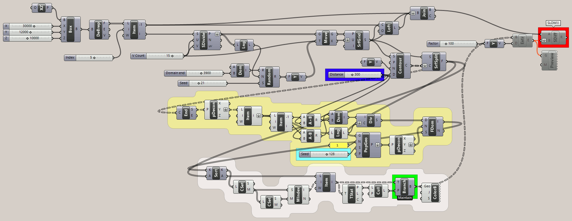
SrfSplit is the first bottleneck I’ve found so far… 1.4 minutes. OK, so instead of culling every other result from SrfSplit, I’m guessing that you expect every other Y value to be culled?
Really sorry about the file, I am just loading it up to try and disable the more intense components and give a more simplified file.
As far as I’m aware there are no errors with the file, but again I’m very new to using Grasshopper so there might be something I have done wrong to slow the file down.
But yes that is correct I want to cull every other contour like this
Best to work at a lower resolution with all the “heavy” bits disabled.
I’m not sure “every other contour” is realistic since some contours have more surface sections than others. And some surface sections have one edge while others have two.
Here is the updated file with the more intense components disabled. Timber_Wall_Aesthetic.gh (11.5 KB)
I see, just about of curiosity what is the closest you can get to the effect shown in my previous reply? or is what I have done the best you can achieve due to the randomness of the contours?
It was way too late for me because I was already heavily invested in modifying the file and didn’t want to start over. I’m almost embarrassed to say how many different failed paths I explored to solve this one. Even now, I believe there is still a flaw…
I used a “low resolution” of 300 on the Contour ‘D’ (Distance) input instead of your 100, It’s considerably faster so will post the file that way, though this image uses 100 which takes a couple of minutes (not includingSDiffwhich I haven’t tried yet!).
Trying SDiff now at ‘D’ = 300, it is painfully slow(5.1 minutes) and the result is a fail. Oh, I see why, the SrfGrid was not joined with the other surfaces to make a solid. (Closed Brep)
Why are the box dimensions so extremely large? 30000 X 12000 X 10000!?
Yeah, sounds simple when you put it that way. I won’t tell you about all the other ways I tried and failed but if there is still a flaw due to area centroid not being on the surface(?), I will try one more idea using PopGeo to place a single point anywhere on each stripe and using that instead.
Still waiting for SDiff to complete using the ‘Closed Brep’… Might revisit this tomorrow. Oh no! I just realized that the input to SDiff is not flattened.
P.S. Come to think of it, the problem (if there is one) may not be the area centroid but failing to find the correct domain. I added an extra domain at one end of the range but maybe the wrong end or maybe both ends are needed? That part is tricky too.
in my mind most of the suffering comes from the use of the Contour component to generate the section curves using that component implies that once the Y domains are generated, we need to add an extra domain to the start and another extra domain to the end, to include also those super tiny trimmed surface-end islands
my first thought was to use the classic XZplane array along Yaxis + planeBrep intersection to generate the contour curves (instead of Contour component) in such a way to already get the consecutive domains directly from the cutting planes Y values: you end up with a lot of domains that contain nothing, but for sure you have also all the domains that contain something
this alternative is for sure not an improvement, is just a different way to get there
(final curve trees would be the same, but reversed in order)
An extra domain was needed at both ends of the range since surfaces can extend above or below the contours.
PopGeo works better than Area ‘C’ (Centroid) both because it’s faster and because the random seed allows the reference point on each “stripe” to be moved around, which affects results. The ‘Seed’ slider (cyan group) may need to be adjusted to avoid adjacent stripes.
I tried SDiff at 300 and it took two hours! It appears flawed and wasn’t worth the trouble. I suggest using an even lower resolution (like 500) to experiment with it further, perhaps positioning the extrusions to start above the surface and go deeper?
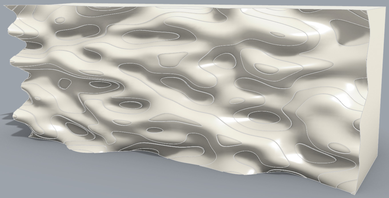
I just want to say thank you to everyone who invested the time to try and find a solution. I have learned a lot just reading everyone’s solution as I’m still getting used to components. Although it is not perfect I can work with what Joseph and Inno have presented as I am happy with the result
I’ve been experimenting with SDiff at various “resolutions”: 300, 500, 600 and 100 units between contours, including making the extrusions thicker and moving them so they “stand proud” of the surface to avoid ambiguity. All are slow (100 hasn’t finished yet) and all have failed in parts.
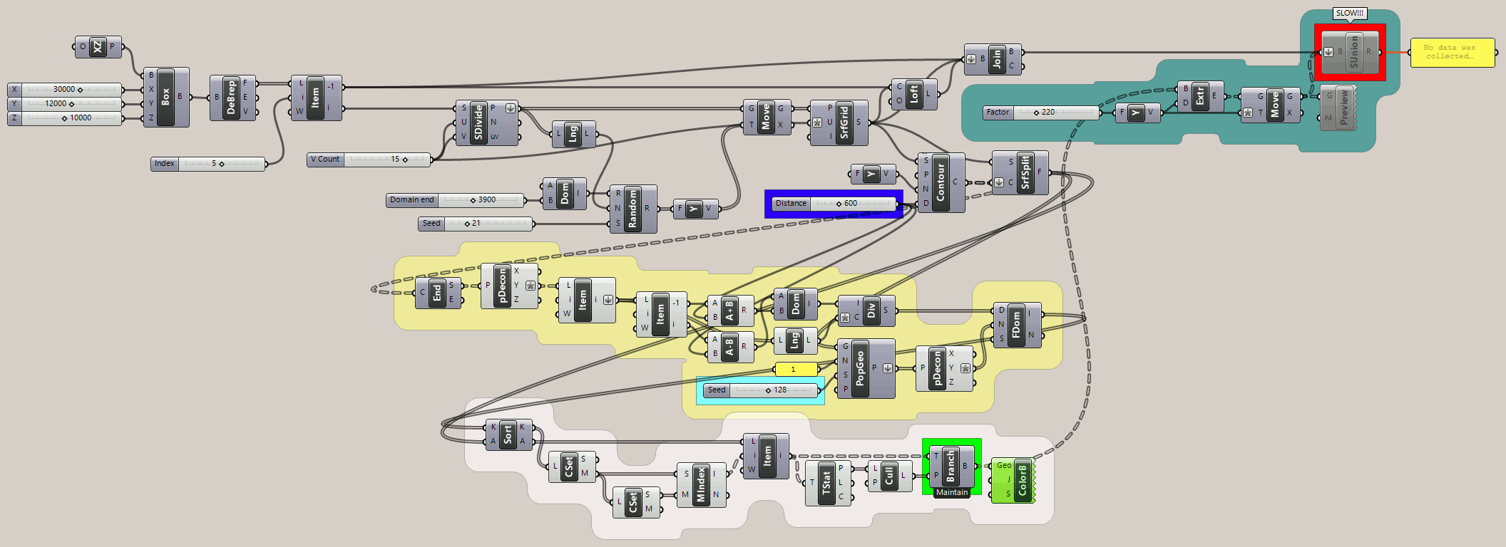
Then I got the idea of replacing SDiff with SUnion(Solid Union), which was a trivial change since the extrusions already extended above the rippled surface. At 600, it was relatively fast (less than 30 minutes but I forgot the actual number) and appears to be 100% accurate!
I’m going to try again at 100 units between contours but can’t help wonder if this might look better with less severe ripples on the SrfGrid? That would require smaller values between contours and on the extrusions.
P.S. At 100 units between contours and 140 on the extrusion slider (70 below the surface and 70 above), SUnion failed after 10 minutes. Possibly due to the steep ripples and inadequate depth? Experimentation with all parameter values is called for.
Also, there is still a flaw with adjacent strips not being culled properly. A better algorithm is needed.
I tried reducing the ‘Domain end’ slider for Random from 3900 to 3000, using 100 units between contours and an extrude factor of 140 (70 above rippled surface and 70 below). I see many broken contour lines that fail to slice the rippled surface as expected.
But went ahead and tried SUnion anyway. It took 3.1 hours and the internalized brep result is 41 Mb! So there’s lot’s of room for improvement yet in achieving this goal.
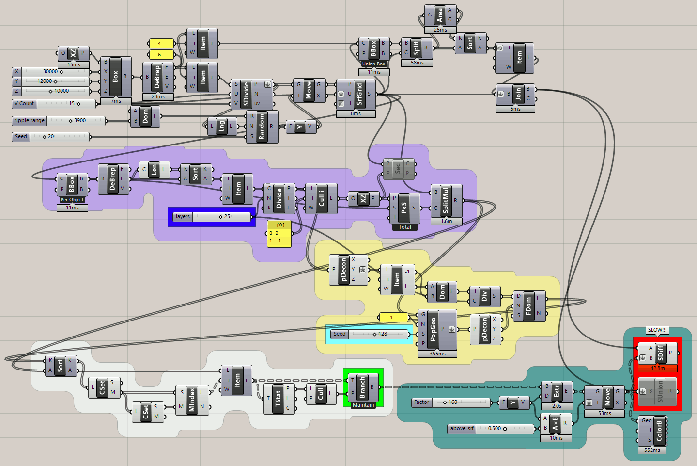
I made some significant changes, including splitting the original box with the rippled surface instead of using Loft. I use a Bounding Box around the rippled surface and divide one of the short edges (see ‘layers’ slider in blue group) to make PxS(Plane Through Shape) surfaces to split the rippled surface. (instead of contour lines)
I added a 0 to 1 ‘above_srf’ slider (teal group) that determines what portion of the extrusions extend above the rippled surface while the rest remains below the surface.
What I found is that three different methods fail to split the surface properly!? Contours, plane intersection and split brep all leave gaps in some cases where there should not be any. This has the consequence of splitting the rippled surface so that some adjacent strips become a single surface fragment that extends across more than one level, which wreaks havoc on the culling.
Even so, both SUnion and SDiff work rather well, taking ~41 minutes each to modify the solid.
I think this is the best result I’ve seen yet. I discovered that inverting the SrfGrid ‘I’ (Interpolate) input to True (default is False) reduced the failures to slice the rippled surface. It didn’t quite eliminate that possibility though, unfortunately, and it created a problem with slicing the box brep with the rippled surface that required some rework there.
This is 25 layers. SDiff works in ~43 minutes. There is a ~1.6 minute delay opening this file.