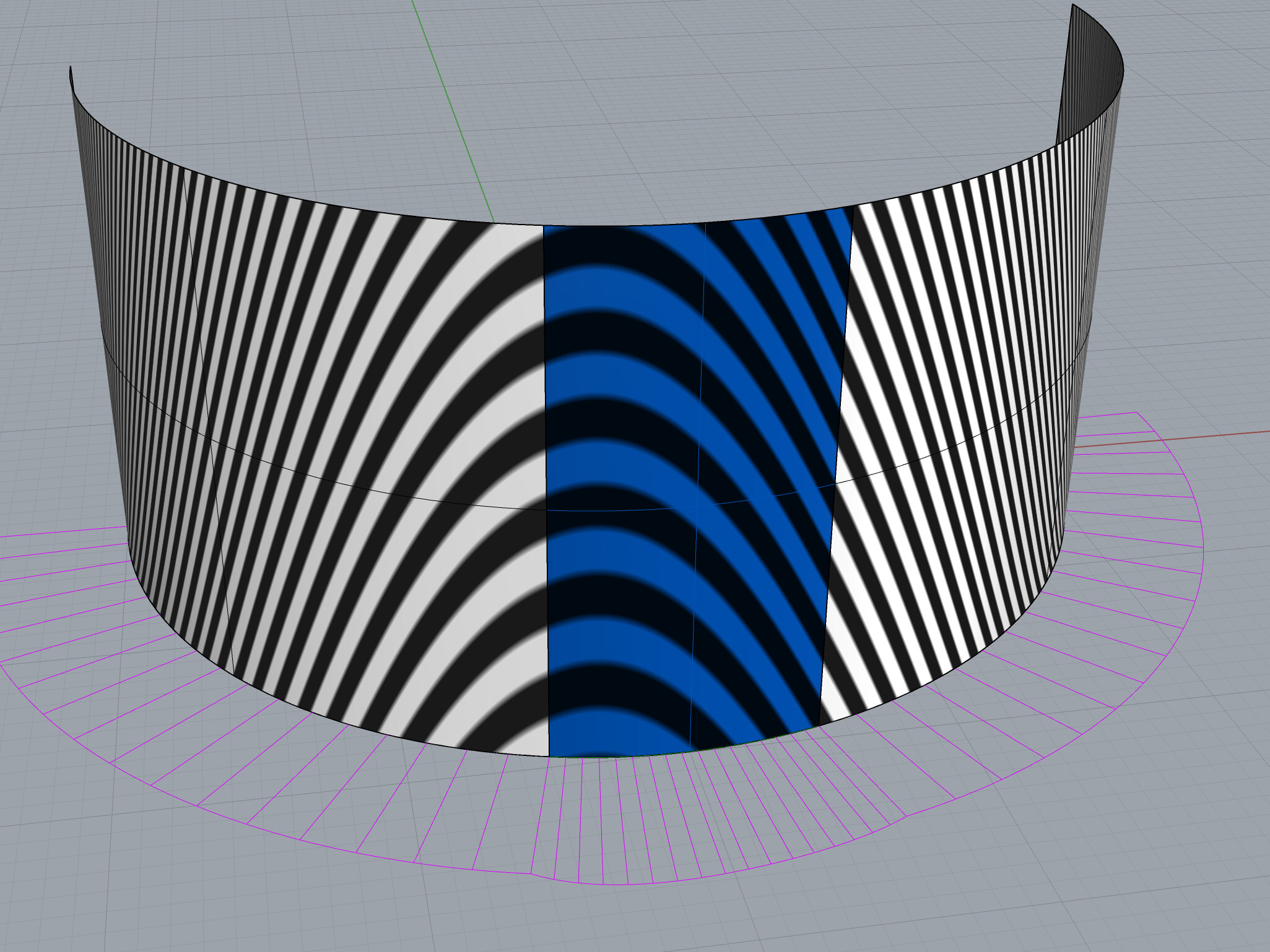
In the latest WIP version, the new Patch command has a new method to match surface curvature continuously, also known as G2 matching. The new method uses two tolerances for curvature matching:
- relative curvature tolerance
- zero curvature tolerance
In this post, I will go into some depth of what surface curvature is, how this new method works, what sensible defaults are for the two tolerances, and why it was introduced.
Curvature
Let’s start out by saying that surface curvature can be a difficult topic - I struggle with it regularly  Having said that, let’s dive right in:
Curvature is a measure for how the surface curves in a direction in the tangent plane of a point on the surface. When you use the Curvature command in Rhino on a curved surface, you can see the minimum and maximum curvature radius as two arcs that change as you move the point around on the surface.

Minimum (green) and maximum (red) curvature on a point of a surface. The arrow and yellow plane indicate the normal direction and plane at the point.
The curvature changes from minimum to maximum radius as the direction is rotated around the surface normal. Curvature is obtained as a vector K, and the length of that vector, k, is inversely related to the radius of curvature:
|K| = k = (1/r)

The pringle-like shape indicates how the curvature changes around the normal
Because the k-value is related to the radius of curvature, scaling an object by a factor of 3 will also increase the radius of curvature by a factor of 3, and because of the formula above, decrease the curvature k-value by a factor of 3. In other words, curvature is dependent on the size of the object.

Curvature evaluated at the same position on a curve scaled by a factor of three: The radius increases, k-value decreases.
Comparing curvature
When Patch is matching the curvature, it tries to match these curvature k-values, so there are always two curvature values in play: let’s call them k0 (on the edge being matched) and k1 (on the patch). To compare these values in a way that does not depend on the size of the object, we calculate the relative curvature deviation (let’s assume that both k-values are not equal to zero, we’ll get to zero curvature below):
d_rel = |k1 - k0|/max(k0,k1)
If k0 and k1 are equal, d_rel will be zero, and if k0 is 5 times larger than k1, d_rel will be 0.8. As k0 and k1 become more different, d_rel will get closer to 1. What is nice about this way of comparing curvature is that it is independent of the scale of an object: if an object is scaled by a factor of 10, both k-values will be scaled by a factor (1/10) and these will be canceled in the fraction in the formula for d_rel:
d_rel = |0.1*k1 - 0.1*k0|/(0.1*max(k0,k1))
      = (0.1)*|k1 - k0|/(0.1)*max(k0,k1)
      = (0.1/0.1)*|k1 - k0|/max(k0,k1)
      = |k1 - k0|/max(k0,k1)`
Zero curvature
The formula for the relative curvature deviation d_rel (see above) is not suitable if one or both of the k-values is equal to zero. If one of them is zero, d_rel is always equal to 1.0, independent of the value of the other, and if both are zero, a division by zero occurs and that is always problematic.
This is where the zero curvature tolerance comes in: when comparing curvature, we first check if the values are less than the zero curvature tolerance, and if so, their values are set to zero. Only if both values are not zero, do we use the formula for d_rel.
Detailed steps
So, it comes together in the following prodecure:
-
Check if the k-values are zero
k0 = k0 < curvature-zero-tolerance ? 0 : k0
k1 = k1 < curvature-zero-tolerance ? 0 : k1 -
Use the following table to decide what to do for calculating the curvature match:
curvature-match? |  k0 = 0      |  k0 > 0       |
-------------------------------------------------
          k1 = 0 |   yes        |   no          |
-------------------------------------------------
          k1 > 0 |   no         |   see below   |
-------------------------------------------------
- If the table above did not give a yes/no answer, continue.
- Now
k0andk1are both larger than zero, so we can safely use the formula ford_rel. If the value ofd_relis larger than the curvature relative tolerance, there is no curvature match. If the value is smaller thand_relthere is one more check: the direction of the curvature vectors should also match: - A curvature match is only found if
d_rel(k0,k1) < curvature-relative-toleranceand ifangle(K0, K1) < angle-tolerance.
Sensible defaults
Curvature relative tolerance
The current Patch command uses a default relative curvature tolerance of 0.05, which means that the k-values may have a difference of up to 5%. If your curvature continuity requirements are not very strict, you can increase this to 0.1 without losing a nice-looking light lines flow.
Curvature zero tolerance
This is still a scale-dependent parameter, which says something about the curvature radius above which a surface can be considered flat. The current default is to use the same value as the document absolute tolerance. If this value is 0.001, it means that curvature radii above 1000 are considered flat. A good choice depends on the scale of your model and your curvature continuity requirements.
Why this change?
Up until now, Patch in G2-matching mode required you to come up a tolerance for the difference in curvature k-value d_abs = |k0 - k1| and if the absolute difference between k0 and k1 was below that threshold, the curvature was said to be matched. As explained above, the values of curvature are dependent on the scale of the object, so you had to come up with a value that you thought was suitable, both for the scale you’re working at, and for the curvature continuity requirements of your project.
We think that using a relative curvature tolerance is easier to understand (even if we need this wall of text to explain it all) and thinking of a curvature zero tolerance for the model you’re working with is easier than coming up with a scale-dependent value for d_abs.
Analyzing curvature continuity
There are a few ways to analyze curvature continuity in Rhino:
- Zebra
- CurvatureAnalysis
- GlobalEdgeContinuity
- EdgeContinuity
The first two are visual analysis modes, showing light lines and color-mapped curvature values. The last two are numerical analysis modes. The latter does not (yet) have the method of comparing curvature as explained above.