Please tell me which values should be set up for high-quality continuity on EdgeContinuity command.
I`ve heard that those default ones are draft ones and for production, it’s needed to set it up more strictly. Please tell me what tolerance value is demanded to distance, tangency and curvature continuity (G0, G1 and G2).
Edit:
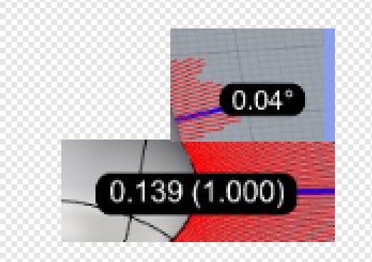
Please clarify me also why on tangency black label is the visible degree and on curvature black label is visible max distance. I’ve thought that on both cases should be visible same data on black labels. Isn`t it?
Please tell me what is that 0.139 on curvature tolerance? Is it distance or degree? There is no degree sign so I assume it`s a distance. What that (1.000) means?
So position (G0) and curvature (G2) has got distance values over the black label and tangent (G1) has got angle there?
Please clarify me which values are demanded by G1 and G2 on black label (production quality)? Please tell me also what data should I put to distance tolerance, tangent tolerance, and curvature tolerance fields to have non-draft quality (enough for higher quality but without overshoot - production grade).
In other words: which values I should put there to all people who will see my design later not argue that is not G1 or not G2 because their continuity is too draft and quality is too low. Is there any universal data like this?
I wonder if it`s possible to translate those values to get some some universal data on EdgeContinuity command which will be correct in most real life cases.
I’ve asked also because in Gcon (works on curves) Rhino says which contuity is that:
Rhino says is it G0, G1 or G2. So Rhino judges which type of continuity is the closest one. I’ve thought that in EdgeContinuity also will give me some advice. After seeing those data I don’t understand what values I should have on black labels to have what I want to have. I don`t know also should I change or should I leave values in tolerance fields put there by default.
Is it possible to see some tutorial (free or paid) to see how to use EdgeContinuity command in real life scenarios?
Edit: In other words, I try to learn how to use that EdgeContinuity command but I don`t know how to properly use it and which values should I change to judge is it G0, G1 or G2 continuity.
I would like to ask also about default values on tolerance fields. Do they mean something? Because now curvature tolerance is the highest number. I’ve thought it should be opposite.
Please look at the image. Green lines indicate that curvature is ok and there is no even position because it’s a gap. So I looks like it indicate wrongly on default values. I wonder maybe there is some error values on those fields. I’ve thought that curvature should have the smallest tolerance number because it`s most strict. Isn’t it?
May somebody tells me what tolerance values should I put into the distance, tangent and curvature fields to have proper colouring over parts which will have from few cm to 3m? May somebody tells me which max values taken from the black label is border value between G0/G1/G2? May somebody clarify me how to use that EdgeContinuity command in a real-life scenario?
Default values don’t make sense for me. For example It indicates green with a gap what is not ok. I don`t know how to set it properly.
My target is rather clear. I would like to be able to judge is that surface connection is G0,G1 or G2. I would be grateful for any help.
I bought Rhino 7 upgrade yesterday mainly for that command and I don’t know how to use it :).
I know base idea of that but when I try to use it color indication are indicating badly. I don’t know also how to interpret values from black label (is it still G1 or maybe it’s too low and it`s G0). Please help me.
Here you can see default values of match surface command. Maybe the same values should be placed in EdgeContinuity command as default values (distance tolerance, tangent tolerance, curvature tolerance). What do you think about it?
and I think that EdgeContinuity default values (with mm template) should looks like that (Rhino with default tolerances):
I`ve set distance tolerance as 0,002 because joining will fail after crossing 2x default absolute tolerance set up in properties. So if there is 0,001 then here it should be 0,002. Am I right?
Those settings look good if you are trying to match the document’s tolerances (absolute of 0,001 and angle of 1°) from one of the “Small Objects” templates. But are those tolerances good for your clients and downstream processes?
_GCon’s labeling of curves being G0, G1, G2, or “Curve ends are out of tolerance” are in reference to the document’s tolerances.
@pascal What should be Curvature tolerance by default with default Rhino settings (EdgeContinuity) because 5 looks like out of space. Should I put there same as default MatchSrf = 0.05? Maybe it supposed to be 0.05 and 5 is only by mistake or something?
Absolute curvature deviation is more meaningful when all the radii are about the same. For example, the following pairs of Radius1 and Radius2 produce about the same deviation, ~0.001:
1.0, 1.001
2.0, 2.004
4.0, 4.016
10.0, 10.1
100, 111
It may be more useful to replace the Absolute curvature deviation with Absolute radius deviation and more intuitive to replace the Relative curvature deviation with Relative radius deviation,
abs(Radius1-Radius2)/max(Radius1,Radius2).
Please tell me: Has curvature input field value (from MatchSrf) same type of value as Curvature input field from EdgeContinuity? If yes, then I assume that both values should be the same by default. Am I wrong?
_MatchSrf’s Refine match Curvature unit is percent, so it may be the same as _EdgeContinuity’s Relative curvature deviation, the value in parentheses.
Due to how the size of the radius affects the Absolute curvature deviation, I recommend that you ignore the color coding for curvature and instead focus on the values in parentheses.
I have one question more to that EdgeContinuity Curvature relative deviations (in parentheses):
I’ve created a surface with blendsrf (curvature). After moving CP value inside parentheses is not changing. It has got value equal 1.000 all the time. Why it`s constant? Is it a bug or correct behavior?
Why after refining match with 0.05 value I can’t meet that curvature value in EdgeContinuity (value in parentheses). I have always more than 0.05. Is the same value or I’m doing something wrong? I`ve tried also rebuilding and matching after without refining turned on, also without success.
Hello .
the absolute deviation is the most important to assess the continuity of curvature.
but that does not ensure the good qualities of the flow of continuity between the surfaces.
the zebra is useful for evaluating the qualities and aesthetic appearance of surfaces …
one thing to note is that if the tangency is not good the curvature will not be as good.
to assess the quality of your models You have to start by checking the distance and then the tangency followed by the curvature.
0.5 ° in tangency is a correct value for good surfacing. for high quality surfacing 0.05 ° is an absolutely strict and high quality values.
for curvature values between 0.1 and 0.05 are fine. between 0.05 and 0.001 these are really high quality values.
on the other hand, you should know that the numerical value of curvature does not guarantee you the good aesthetic aspects as I said before. the numerical values of curvature do not really have the same importance compared to the values of tangency. and distance. the latter two are used directly for manufacturing


 and I don’t know how to use it :).


