I received an .igs file of a ship hull which contains a lot of surfaces and I would like to create a solid out of it for further processing purposes. There is a layer in the IGES which I don’t need (container on top of ship, therefore I removed that and closed the geometry with two planar surface. I can create a closed poly-surface from all the surfaces, however Rhino is unable to create solid.
Can you help me find what is the problem? I am looking at it with the edge tool, but there is no naked edges nor any manifold edges so i think it should doable.
… on Rhino, a solid is a closed polysurface, and vice-versa.
Can you explain where is your problem? What you mean with “solid”? What are you trying to do?
I’ve opened your .3dm and it seems indeed a valid closed polysurface.
Thanks for the quick replies. I see you are right and my problem lies later in the process.
I am trying to create a good geometry for meshing with gmsh and what proved to be a good approach is to create an .stl file as a surface mesh and from there gmsh can create the volume mesh. This worked for simple geometries (now I see it works for closed poly surface as well) but not for this geometry. Any suggestion what would be a good method?
My overall goal is to create tetrahedron elements of the closed geometry. If this can be achieved in Rhino itself that would be even better.
Hi @farkas.beothy
I would try and open the resulting STL file in Rhino and check for any errors (naked and non-manifold edges, duplicate faces etc.) using MeshRepair - or maybe mesh it “manually” in Rhino using the Mesh command, check the resulting mesh the same way and then export that mesh as STL.
HTH, Jakob
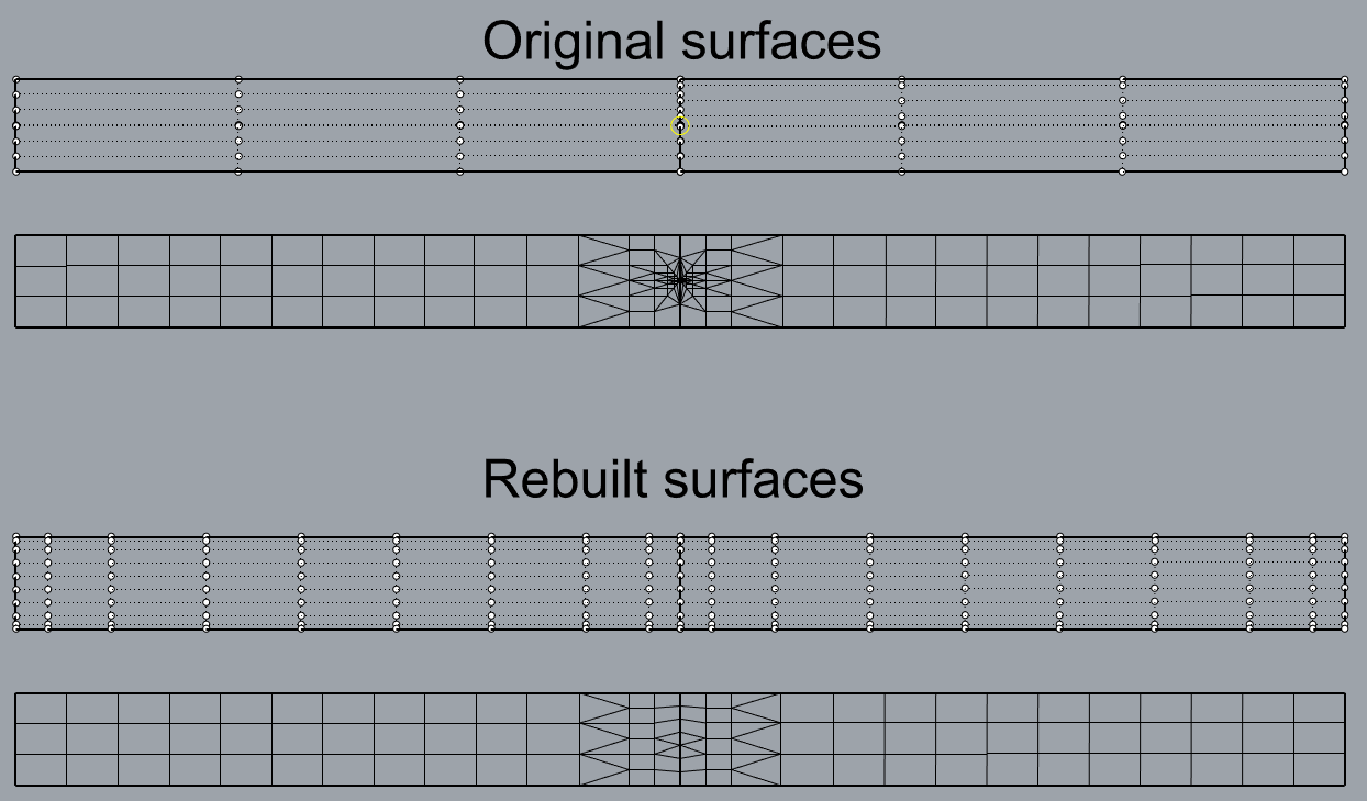
Your surfaces have many, non uniform and sometime even congruent control points!
This lead rhino meshing go crazy and make many small edge, resulting in a problematic mesh.
That situation comes directly from the iges file…
2nd row: in the joint between the 2 surfaces the mesh have very small edges.
3rd row: rebuilt surfaces, now they have even control point distribution
4th row: meshing result in a more decent mesh
Zremesher in Zbrush (I like zremesher in Zbrush but Rhino also has it)
It’s still not perfect but after adding extra loops on the hard corners it will be enough for subd smoothing. After that, you will have a perfect smooth render or 3d print (after freezing and decimating). I am writing about that because only after decimating lights/shadows looked ugly. Best would be manual polygonal retopo what on that model won`t be so hard in Modo/Blender.
@maje90 Thanks, this seems to work. I played around the rebuild parameters and I managed to create what I needed with this method. @mdesign Thanks a lot. I can use this mesh as well after some more processing.