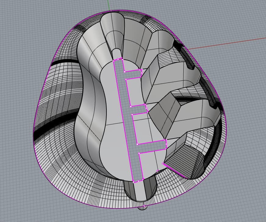
Hi all, I have completed my surfacing model and wish to convert the model into solid with thickness of 1mm.
I have tried to offsetsrf, but it produces many naked edges difficult to repair. I have also tried to offset the surfaces exploded before blending, loose=yes, which yield surfaces that intersect in such a way that is difficult to split.
Are there any other commands that are more appropriate, or my current model needs a rework eg, more allowance of higher radius of blend.
Am I right in assuming you are trying to offset your surface “downward” -away from the viewer- in the view you attached? If so it is no wonder that you are having the problems you describe.
Offsetting in that direction requires everything to “get smaller” as you try to compress all the features into less space. Try offsetting in the other direction.
Of course if the surface shown has been carefully designed to be the “top” surface then what I’ve suggested won’t get you what you want but it will illustrate my point. Not that it will be perfect since there are some features on the upper flat surface that might have issues.
Another thing you might consider offsetting before applying all the filleting. Sure, it doubles the amount of filleting you need to do and would require you to calculate the proper fillet radii for the offset surface but it might prove far less challenging for the offset command.
Hopefully others here with more offsetting experience will chime in with more detailed suggestions.
Perhaps you would like to post your starting surface file (both before and after filleting) for the offset command developers to add to their “improvements” wish list collection?
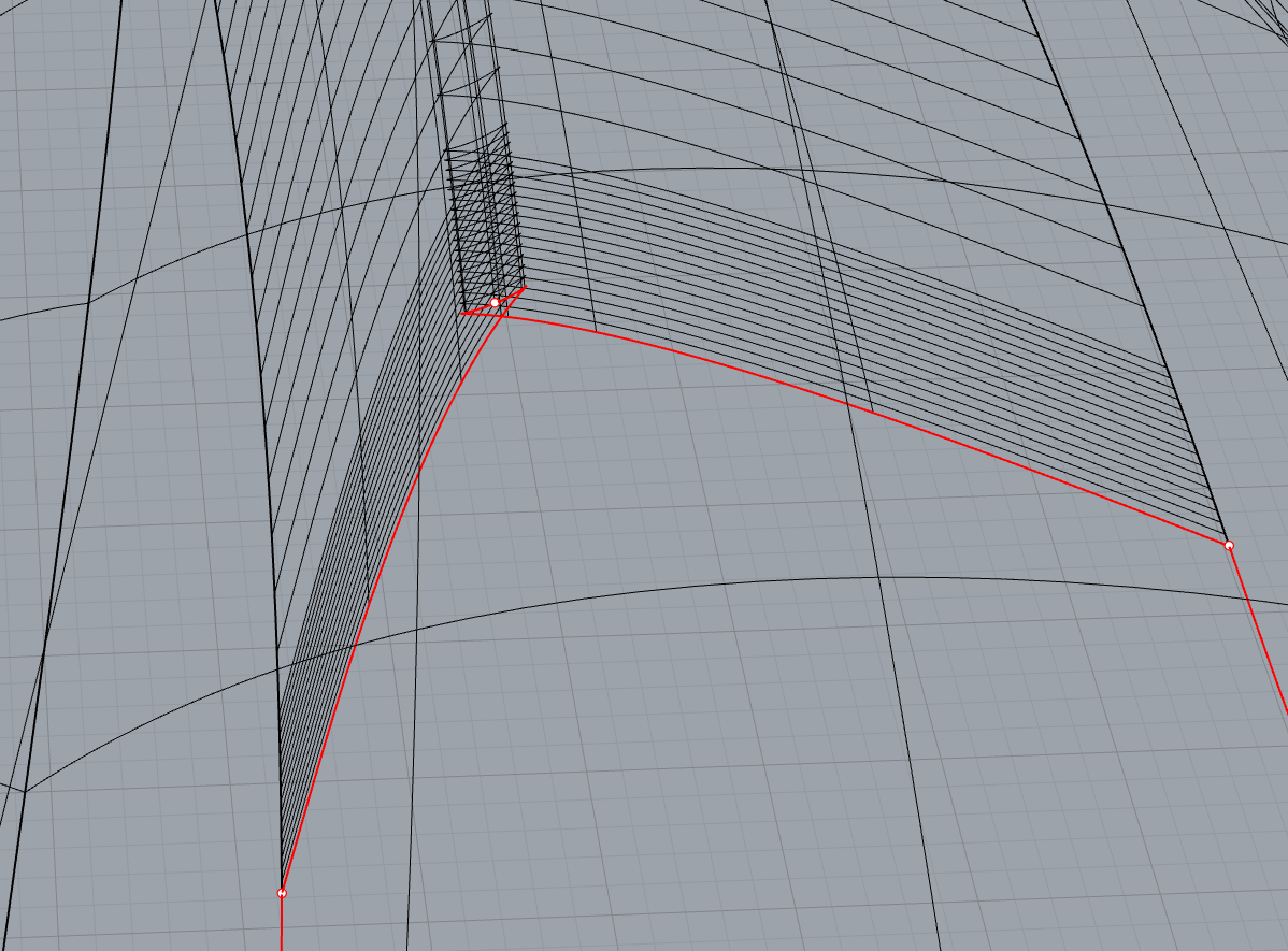
Hi Hagen - it is a tricky one - the blended 6-patch corners look hard but as well, you have some surfaces where the radius drops below the offset distance - that is tricky as well and you can get reversals like this
Thank you for the response. Yes I have designed the surface shown to be the top surface and thus I am offsetting downwards. I have noticed that offsetting inwards, will result in surfaces that warps inward, thus unable to manufacture.
Hi Pascal, thank you for the response. I will attempt to re blendedge to find out the correlation between the radius and offsetsrf. The current radius for all the surfaces are at it’s maximum, thus I can only try a blend of lower radius.
I would like to enquire also if it is better then, to rebuild the 6-patch with the Patch command, so as to reduce the number of surfaces and edges?
The problem is going to be, I guess, that you cannot tell from the input radius what the minimum radius of the blend will be - it may take some experimentation. You can check existing surfaces by extracting isocurves and running Radius to try to locate the minimum.
I make be wrong about the 6 patch corners - at a larger radius it may offset reasonably well - it’s just that all of this is trickier than with constant radius fillets.