Have you any idea of how to create a surface with these curves ?
NetworkSrf doesn’t work. Sweep2 neither.
Does someone knows similar examples ?
Do I have to decompose the surface in smaller surfaces built with NetworkSrf or Sweep2 ?
I’ll be glad to know your point of view.
Thanks a lot !
There is no surface command in Rhino you can throw curves at willy nilly, and get a good surface model.
Certainly the general shape is implied by these curves, but you’ll need to apply a strategy based on the input curve requirements to chose which specific curves are needed, and go from there.
It’s like golf. Each shot requires all of the right elements to come together in the right order.
I see a revolved surface, several capped lofts, then some guessing where blends go to result in something that would fit those curves.
Hi Fer Di - this appears to be basically a Revolve of one od the curves and the four protrusions blended in to that. This would be made in several stages, there is not one command to get it all done.
Terry I’m now travalling I can’t send you the.3dm .
For the moment, my conclusions are the same as you. Nevertheless the difficulty is still to draw the protrusion, and especially their junction with the revolved shape. I dont’t think that a bolean operation and a Fillet will work fine.
I’ll give you news when I’m back, in a few days.
Thanks again
Its just in Rhino. I wouldn’t know what could be done in Tsplines.
To make this is mostly just point editing. Actually, just raising up some of the points.
I started with just one quarter of the part and used array polar and MergeSrf (smooth=no) to make the whole surface after I finished point editing 1/4 of it.
In the enclosed file the blue surface on the right shows what I started with before any point editing. On the left the red curve is the intersection between the fl;at top and the protrusion with history enabled so that it is possible to see the shape as you point edit. Single_Srf.3dm (281.9 KB)
Here is an 88-line Python script that will create one surface for the tray-like object using curves. It was done with 1 revolve for the base and 1 loft for the foot to make 1/4 of the tray which was then copied. All the dimensional parameters are at the beginning of the Main script for easy modification. The dimensions are similar to those used by jim while the shape of the feet are more elliptical like in Fer_Di’s drawings.
NOTE: The first version of the script below is for Rhino6 WIP, the second for Rhino5. This was due to differences in defining elliptical shapes in the addGuideCurve procedure.
Thanks a lot again,
Actually I’m trying to reproduce a foam model and I need the curves to be very close to the model’s one.
@Terry_Chappell, this script is impressive and vey efficient, thanks. I don’t how I can edit the coordinates without taking too much time.
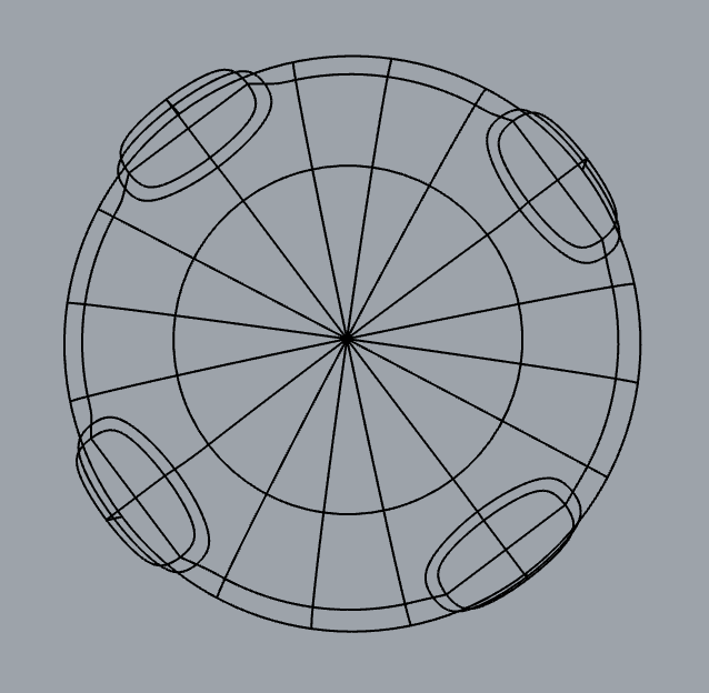
@jim this way looks perfect for me. I don’t know how you did to have so much control points on your ellipsoid. I just have a few. (cf. picture). Is there a way to add control points ?
I am back from my trip. I updated the script to more closely match your dimensions. I have included scripts for both Rhino5 and Rhino6 WIP. The Rhino6 script includes a curve shape parameter that works over a wide range. This makes it easier to adjust the shape of the foot curves.
In my workflow there is no need to prompt for coordinates as the script is open for editing while observing the results. I just change the script, push Ctrl-s to save it and then F5 to run it and see the next iteration. Very fast. Many of the procedures and steps used in this script were taken from proven examples in my other scripts. This saves significant development time.
See picture below of my work flow with viewable results on the left and the open script on the right.
Thanks a lot Terry. I’ll try it tomorrow, this looks amazing.
Point editing worked really good, it’s a smart way to do fast it but it isn’t very rigorous. I’m waiting for a print to check render on a tangible model.
I have updated my scripts to eliminate the small, 100 um z-offset in the position of the foot. This was previously done so that the foot would intersect the base in a single curve as required for their Boolean union. Now I have found a way to avoid this z-offset. The details are described in the comments of the script.
The Rhino5 script still has a small x-offset of the foot from the edge of the base in order to keep the construction shapes from falling off the base. In Rhino6 WIP, the x-offset can be zero. Rhino6 WIP is much nicer to work in than Rhino5. Hopefully it will be officially released soon.