Two years after the first project the G150 was drawn, (1996) I decided to continue to fly along that track but this time working on a brand new idea. A kind of concept radically review of the originate G150 that would take me up to the next level was my next target, designing a brand new aircraft, wider than the G150 with at least four seats. The G416B is indeed quite compact provided of a different type of propulsion technologically affordable at the time since the way I imagined electric motors wasn’t conceivable yet in 1998 I take the Hybrid option as the main platform to work on developing a machine more realistic at least in the late '90s. The G150’s project was in fact partially solved right since I had no idea of what kind of electric motor I could find to install in that aircraft and only some years later in 2003.
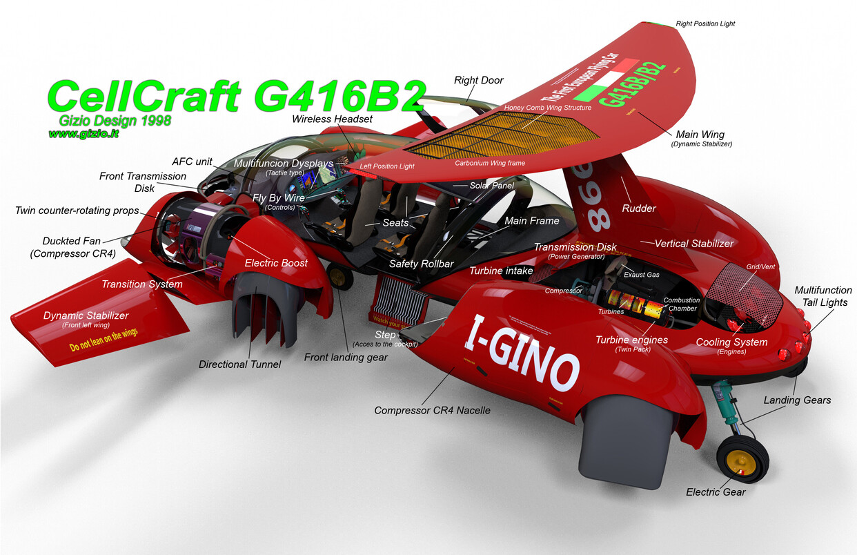
The G416 was rather a hybrid aircraft provided with a transmission system and electric motors inserted in the compressor rotors. Two turbine engines were adopted to run four compressors that were connected through a special transmission system. Those mechanic couples were provided with an electric generator that would power in addition the four electric compressors during the forward flight to save fuel since transmission in that phase of the flight were not necessary and then was always disconnected. While during hovering or vertical take-off or landing the whole system transmission/electric motors could work together for a limited time not more than five minutes in hovering at maximum power ratio (110%) indeed both the electric motors as well the transmission was engaged at the same time.
For this aircraft, I employed two turbine engines with a power ratio of 440 Hp/ 328 Kw over-powered by a couple of electric motors** mounted inside of each compressor (Ducted Fan). **Electric motors would provide additional power when required. The whole system Turbines engine/electric motor via mechanic transmission would then discharged on the four ducted rotors all the available power at least in hovering flight or for take-off and landing.
The G416 was pretty much different if compared to a common aircraft, it was provided with a big transparent dome, with a wide area covering over 35 percent of the whole aircraft surface. Another point as well important about this project, and those who followed it later was also taking the advantage of the aerodynamic shape of the whole fuselage’s surface in order to increase aerodynamic efficiency and lifting capability. The engine compartment was settled at the rear of the main body of the aircraft, actually under the main wing attack, pretty much in correspondence of the center of gravity, which in this aircraft was pretty much aft shifted.
Compressors or ducked rotors were all housed in four nacelles, arranged on each side of the fuselage. The Ducted rotor or compressor’s internal chamber reminded that of a Venturi’s tube profile, inside of which were housed two large counter-rotating fans connected to the disc transmission system through tubular shafts, furthermore the rotor couple were provided of an internal electric motor. The electric boosters were operated only in situations where the required power was necessary as the maximum available at the moment, while in hover flight or during take-off or landing to support the weight of the aircraft in flight at the best.
The interior of the aircraft was initially designed to accommodate five passengers, but in the latest version revisited a year later in 1999 (G416B) all the seats were set down to four to increase space between the passenger and reducing weight at the same time.
The flight management system; the AFC (Automatic Flight Control) was and still is, the main electronic device adopted for perfect control of the asset of the aircraft in flight. It corrects any variations or attitude balancing the position of the aircraft in the space instantly. The flight controls of the aircraft were also integrated on both sides of the pilot’s seat rather than mounted on the main aircraft body, and then was the time when the Smart Chair has born and it is largely employed today in all CellCraft and Verticraft projects of mine.
The control of the aircraft in flight could be done thanks to two different types of joysticks, settled on both sides of the Smart Chair. Both, the yaw control and power would be managed through the action taken by the left joystick, while direction control is settled on the right side. The G416B/B2, the latest version, was equipped with pedals too, however, in some particular situations, the yaw control could work quite comfortable if activated automatically through the small lever placed below the **power control joystick head.
In 1999, further improvements were made to the original project, which became then G416B/B2 with the addition of two dynamic stabilizers settled in the fuselage’s nose. Also the two little front wings as well the main rear wing were both controlled in real-time by the AFC, indeed they were constantly tilted along with the flight in order to maintain a perfect asset at any due condition.
Unfortunately the G416B/B2 even in the better version revisited later didn’t prove any convenience in terms of weight and fuel consumption, it was also too complex in terms of mechanics however it was an interesting machine despite rather inconvenient.
This project was however the spark that lighted up a series of so many projects that came later, it’s a very important step also because I designed a new architecture for aircraft having a structural and a design absolutely compact and innovative. That allowed me to develop more and more advanced aircraft of this type and that could give more room to the technology of electric motors in the future in-fact one branch of my design production is to design some electric motor with a modular disk architecture, quite adaptable for many applications but unfortunately not described on side of this site for copyright reasons.


6 Likes