It’s all about making the existing main modeling tools move versatile and user-friendly. The current implementation of “Blend surface”, “Match surface”, the control point manipulation with the “MoveUVN” tool and the various drag modes. Control point selection ('_NextV, '_SelU etc) is also a big “guess game” due to the lack of proper visual U and V indicators on the surfaces with shown control points.
Example for a lacking functionality #1: No “Explicit control”. This is a hugely missing functionality. It should act like an integrated optional “Rebuild surface” into the major NURBS modeling tools, with the ability to change the degree, control points and spans while those commands are still active. This way, the user could set a custom degree and number of control points while using “Blend surface”, “Match surface”, “Sweep 2 rails”, “Sweep 1 rail”, “Loft surface” and “Network surface”, eliminating the need to modify the resulting surfaces subsequently and then apply “Match surface” again.
Example for a lacking functionality #2: If I start the “Blend surface” command, Rhino will not let me activate the Zebra analysis. If I apply Zebra analysis to target surface A and then start the “Blend surface” command, Rhino will apply Zebra Analysis in the resulting preview of the blend surface, but will not apply it to the opposite target surface B. In order to see a full Zebra analysis, I’m forced to preliminary apply it to both target surfaces (or multitude of surfaces). The latter is especially disturbing when I have several surfaces chained together via the “ChainEdges” option, because Rhino will refuse to show Zebra analysis to any of the input surfaces that were not included in the latter preliminary. Rhino also cancels the “Blend surface” command if I try to apply Curvature graph to the surfaces while the former is still active.
Example for a lacking functionality #3: “Blend surface” does not have an option to align the end handles to the same direction as the U or V direction of the target surface(s).

Example for a lacking functionality #4: “Blend surface” also does not have an option to align the end handles to the side edges of the target surface(s).

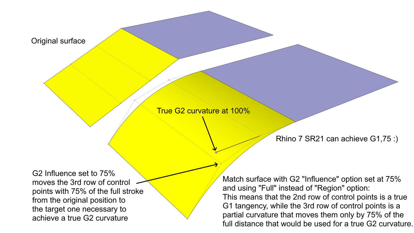
Example for a lacking functionality #5: Both, “Blend surface” and “Match surface” don’t have an influence option to control the amount of modification for the 3rd row of control points. With other words, that option should let the user set a variable rate for the curvature which is greater than G1 but lesser than G2. Currently, Rhino only supports either G1 or G2. The latter is way too aggressive in many cases and this is where the ability to set a custom influence of 50% for the 3rd row of control points would help to achieve something like a G1,5 instead. Also, the user must be able to apply “Match surface” to individual control points, too, meaning he or she could apply that only to a specific region of the surface while the remaining area(s) will not be affected. Example:


Example for a lacking functionality #6: “Blend surface” does not have a real-time adjustable “Planar sections” handle that updates automatically upon changing of the direction (it must be possible to control its direction, both, via X/Y/Z direction, numerical coordinates and manually via the mouse):

Example for a lacking functionality #7: An option to preserve the control point flow of the modified surface while using “Match surface”. This means that the program should try to match the 3rd row of control points in the normal direction, while the changes to the U and V directions should be kept at the very minimum. This may lead to something like a G1,97 instead of a true G2, but the benefits are huge. Here is an example where this option will show its full potential (note the 3rs row of control points):

Example for a lacking functionality #8: “Match surface” could lead to weird results on split surface edges due to its inability to use a single U or V direction. Instead, using the “Match target isocurve directions” option will do its own thing and could use multiple different directions, despite the fact that this particular option is supposed to align the control point flow in the same (single) direction).

Example for a lacking functionality #9: “Match surface” must have an option to project match to a surface (or even two two or more adjacent and tangent surfaces) along the X/Y/Z axis or a custom direction (2-point vector or by picking an existing line). Check this video after the 10:30 minute to see how it’s done in Alias:

Example for a lacking functionality #10: Ability to match a surface directly to a target isocurve without the need to preliminary extract the latter. This should be interactive, meaning that the preview must allow the user to freely slide the matched edge along the target surface following the same shape as its virtual isocurves. Currently, the “Match surface” tool could match to a preliminary extracted isocurve in a non-interactive way.
Example for a lacking functionality #11: Ability to slide the end points of the surface to be matched along the target surface edge(a), or surface isocurve, or curve(s) in a similar fashion like what the handles of the “Blend surface” tool already are capable of.
Example for a lacking functionality #12: Ability to use “Curve blend” to match directly on a surface in a fully interactive way (similar to example #10 above), including two options:
a) Along the U or V surface isocurves (no need to be extracted preliminary), with a Command line option to switch the direction at any time while the command is active;
b) Along the target surface in any desired direction (similar to what’s possible with the handles of the “Blend surface” tool while holding down the Alt key).
Example for a lacking functionality #13: Rhino will not let me apply Zebra analysis while the “Match surface” command is active. Even if I preliminary apply Zebra analysis to all target surfaces, it will not be automatically shown on the preview of the surface to be matched (at least the “Blend surface” tool allowed that).
Example for a lacking functionality #14: Cumbersome drag modes. When I activate the ! _DragMode _UVN , Rhino will not let me use it until I turn off the Gumball. If I try to use the UVN drag mode while Gumball is visible, Rhino will drag along the world XYZ axes instead of the UVN directions of the surface.
Another huge user-unfriendly thing about the UVN drag mode is that tiny edits of the control points are nearly impossible due to the fact that the selected control point could be moved to the U or V direction randomly, so to avoid that I’m forced to zoon-in extremely close to the control point and lose a general view of the entire shape of the surface. To fight that, I’m forced to activate Drag strength and set it to 1-3%, which not only forces me to apply more mouse clicks and to move my mouse at longer distances, but also I lose the ability to properly move the selected control point at the desired increments when Gris snap is active. For example, if I want to mode a control point by 1 mm via the UVN drag mode and my Drag strength is set to 1, I’m forced to precisely watch that I snap to 100 mm in order for the control point to move at actual 1 mm distance.
Rhino does not include arrow handles for the UVN drag mode that could make this mode very user-friendly and intuitive (Gumball itself has an option called “Align to object” that could serve a similar job, but it’s not the same; also, it will not move at exact steps if Grid snap is active, unlike the UVN drag mode that does that properly). I proposed those in my previous post here, as well in another topic a few years ago:
There is also lack of a proportional move/slide along the UV directions of a surface, which should act as Rhino’s ! _Shear command but in a lot more user-friendly way and with far less mouse clicks (take notice how this is done perfectly in Alias and VSR’s Control point modeling). Also, “Shear” moves along a preliminary set single direction, while a proper proportional UV move should slide the control points along the UV direction of the surface itself (or along the control polygon, depending on the option).
Example for a lacking functionality #15: Improper control point selection. Probably caused by some inconsistency with the Z-buffer in the perspective viewport. Clicking on a point (or on a control polygon between two points) that’s located slight behind the surface results into selecting another point instead, which is far away from the point where I click. This bug was reported here and happens all the time while I work with Rhino, leading to unwanted edits and often use of Undo as I’m a heavy user of control point modeling in my workflow:
Example for a lacking functionality #16: General lack of a robust History updating of objects that already have a recorded history. For example, if I build a “Blend surface” between two target surfaces and then rotate one of the latter at 90 degrees, the history-enabled blend surface will update with a different shape compared to a newly built blend surface between the rotated input surface and the other one.
Also, when I apply “Match surface” to target surface A with the “Refine match” option, then I apply it again to target surface B but without the “Refine match” option this time, on certain situations the resulting surface actually gets extremely dense in control point count despite the fact that I opted not to refine the surface.
Example for a lacking functionality #17: The Zebra analysis can’t be optionally locked to a user-set custom direction, in order to remain in the same location no matter the camera angle. The current implementation of the Zebra analysis in Rhino is dependent of the view, meaning that the zebra stripes move all the time as the camera get rotated. Directional Zebra analysis is a hugely missing feature. There must be “Directional” and “View” options for Zebra. Currently, it only has the latter.
Example for a lacking functionality #18: Lack of Light lines. Both, Alias and VSR users have the great advantage to swap between zebra stripes and coloured light lines that could be set to use a different number of stripes and colours. The Light lines must be fully customizable in Rhino: size, number of colours (automatic presets), ability to set custom zolours via RGB numbers, etc. I suggest to also add ability to use the current viewport’s shading or activate Self-illumination (similar to what’s possible with the Rhino materials). Someone with Rhino 5 and VSR should make you a video to show you the extreme usefulness of those fixed light lines whose direction could be changed in real-time via a single rotating handle in the viewport (Rhino’s “Draft angle analysis” has a sort of directional control, but it’s not real-time and requires much more mouse clicks; it will also not update automatically if the curve used to set the direction is being rotated or modified by moving its control points).

Example for a lacking functionality #19: No “Sweep 3 rails” tool. ![]()
Example for a lacking functionality #20: The existing “Patch” tool is far behind the similar tools in other major CAD programs. Even Solidworks which is not a surfacing program has a much better patch tool that does a wonderful job. The xNurbs plug-in is a good example of a proper patch tool.
Example for a lacking functionality #21: Rhino definitely needs a much more capable “Fillet edge” tool.
Example for a lacking functionality #22: Add an option to the “Patch” tool (or the “Sweep 1 rail” one) to accurately use two cross section curves to build a simple surface like this. Rhino’s “Patch” tool at the moment does a somewhat tolerable result after trimming it back with the isocurves of the resulting extended surface:

The video above shows a X-shape arrangement, but Rhino must be able to solve T-shaped arrangement, too. Currently, “Sweep 1 rail” could build a surface from a T-shaped arrangement of two curves, but it adds an unnecessary amount of control points and can’t provide a clean output.
Example for a lacking functionality #23: Fix the ! _OrientOncrv tool in two ways:
a) Allow snapping while picking Base point on curve for the “OnCurve” option from the Command line. Currently, Rhino doggedly refuses to snap during that important moment, so it’s basically impossible to accurately pick the desired intersection base point, as evidenced from the video below at the 0:38 minute.
b) Allow a proper rotation of the resulting curve. Rhino also refuses to do that, as seen at the 1:17 minute of the same video. Instead, it orients the curve at 90 degrees, so I was forced to rotate it manually afterwards. Imagine how impossible would be to do that if the curve was not parallel to the Y-axis. ![]() The “Flip”, “YFlip” and “XFlip” options in the Command line don’t help in that regard.
The “Flip”, “YFlip” and “XFlip” options in the Command line don’t help in that regard.
Here is a 3dm file with the same curves to try those two bugs:
Surface from the cyan and gold curves.3dm (194.8 KB)
