Getting Boolean difference and union to work in a consistent manner continues to elude me, I was finally able to join the ear to the collar using the individual commands. If I can do it, why cant Rhino? I modified my void for the ears a little and now when I run Boolean Difference (delete input) it leaves the void in place. I could deal with having to delete it myself, but when I do, the ear is full again, no void! I really am considering the considerably large bullet of moving to Solidworks. Maybe, hopefully, there are good reasons why it cost so much? The folks here have been exceptionally helpful, but the workarounds indicate to me that they have spent many frustrating hours gaining that knowledge. I’ve attached my test file. The ear isn’t merged with the collar yet as I need three at 120 degrees and I want to ensure that the ear is correct before I array it and union them all to the collar. If I am just doing something stupid, by all means please let me know what it is. I can take it. 
WSP-Collar-IM-3D-TESTING.3dm (355.2 KB)
You need to check that your solids are valid and closed. This is the most common cause of failed booleans. Your fillets are a mess. I have no idea how you made such a mess of them. You also have stacked cv’s and duplicate surfaces.
I can sympathizes with your union issues. Rhino should be able to handle coincidence surfaces.
You don’t need solidworks for this type of work.

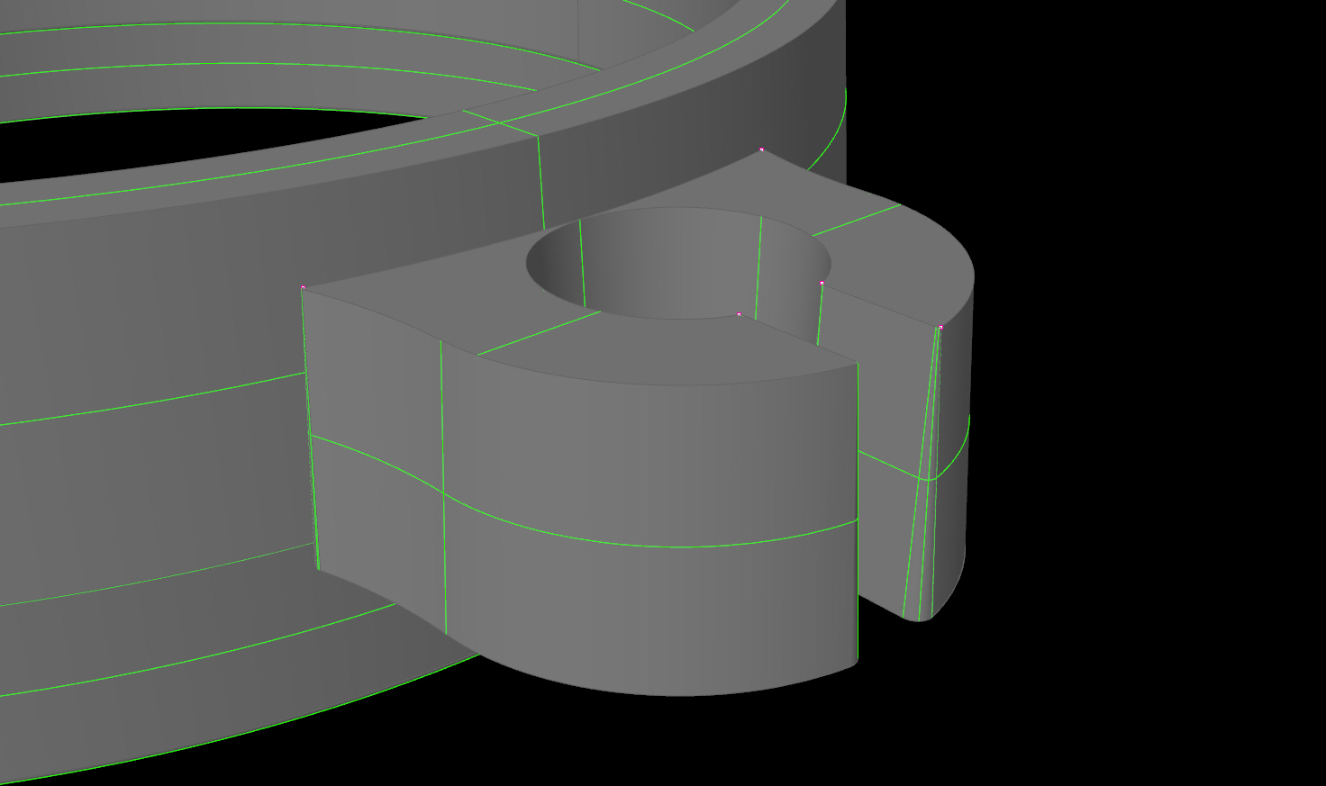
Tell me more. All I know now is that my fillets are a mess. I don’t know which ones or where or how you managed to do what I couldn’t. The only fillets that I did, on purpose were the 15 degree one at the top inside edge, the radii at the corners of the collar cross section, in 2D, before I inserted it into Rhino and revolved it. I did also fillet, with radii the corners of the ear and the void before I inserted it into Rhino and the Extruded them with a 3 degree taper to achieve proper draft for IM. T%he image you attached is what I was trying to do. So know I know that the parts will eventually work. Thanks for that at least.
You gotta practice making cleaner curves. That just means fewer control points and as simple as possible. Why? Your curves are the ‘foundation’ of your model’s ‘progression’:’
- Simple clean curves, make
- clean surfaces, which then make
- clean polysurfaces (or solids) which help
- them join together cleanly, or
- create problem-free details like fillets.
In other words, if your curves are hosed, it only gets worse. Never better.
EDIT: I just read that the curves were imported from another app. I don’t see very many curves, so I recommend you just build it from scratch in Rhino. Its usually faster to make it right then spend hours fixing errors.
Some apps don’t always do the best job or exporting or importing. After an import into Rhino, I’ll check to see what I have … If I explode a straight line – and it’s made of 22 short segments – I know it’s a mess and re-make it in Rhino as a single entity.
Check out this video on Troubleshooting Solids and Booleans. I forget the instructor’s name, but he is damn good.
Each and every curve is either a portion of a circle or a radiused fillet in Draftsight. I don’t know how they can be made much cleaner. You still didn’t tell me what you did to fix my crappy work.
The first step in avoiding problems with booleans is to not use booleans. I do this type of modeling everyday and would never dream of using a boolean.
There is nothing wrong with any fillets in your model. The surfaces that are a mess are not fillets they are surfaces you made with the Tapered extrude command. I would suggest you not put the radius in the corners and then fillet the corners at the end
You need to understand that Tapered extrude is a pretty buggy command and it may take some extra work to get clean surfaces
The enclosed file shows how I would model this. I stopped at the point where you would array the ear. After the array you could boolean. But that’s for suckers.
Just select all the ears and run the trim command and click on the 3 pieces of the ring you want to trim away, then add the ring to the selection set and join everything. Then run cap to cap off all the planar openings.
WSPx.3dm (317.1 KB)
I don’t know what is Draftsight is, but there are lots of little orphaned segments in those curves. Rhino should be able to clean it up with simplifycrv command but that’s another command that needs work.
You need to understand that Rhino is a minefield. if you know how to navigate around all the gotchas you can model anything without getting blown up. if you don’t know you are in a minefield - well you haven’t got a chance.
I should nave mentioned in my previous post that some of your problems originate from the fact that your tolerance is too loose for the size of the features in your model (another gotcha). You have a fillet that is .001" wide and your tolerance is .001 and the top of the ear intersects that fillet. That’s one of the reasons why the booleans are failing.
-jim
I’ve also been struggling with Booleans and am also on the fence about staying with Rhino or going elsewhere as a result – as much as I appreciate other aspects of the product and of Grasshopper.
In this topic, I’m asking experienced Rhino users for their take on whether what McNeel refers to as The Boolean Problems really is as big and hairy as it has been for me and should be given a much higher priority than it currently has.
- Bob
I use boolean from time to time and only have had trouble a few times. When I sat and looked at what I was trying to do I always found it was not
Rhino it was something I was doing.
Rhino is very involved so if you new at it have patience you will end up loving it in the long run.
All my best … Danny
First of all, thanks for all of the good ideas and dare I sat it, sympathy.
I felt like I had stumbled into a minefield and now I find that I have. 
I had decided that drawing everything in a 2D program (Draftsight is an AutoCAD clone) might be part of my problem, so I’m in the process of drawing the profiles in Rhino. I have finished the collar and can already see improvements. I don’t need to MergeFaces to get the bevel right. I’m ready to start on the Ear and Void in the AM.
A couple of things that you should know about me, which will probably explain a few things. I’ve been using AutoCAD since 1982 (R1.4). I was a Beta site for more than five years, so that i something I’m very familiar with. If you like “Stretch”, you’re welcome. LOL I’ve always wanted to get into 3D, but by the time Revit came along, I couldn’t afford me as a CAD operator. OBTW, I turned 70 last month. This project is patented (3+) and I hope to make some money with it.
Thanks again for all of the help and support.
KMAC
Just to clarify my comments: I was speaking of the type of modelling that you are doing - which is modelling parts with draft added.
The people who are telling you that they don’t have problems with booleans are not modelling parts with draft and they have no idea how much that adds to the pitfalls in the Rhino modeling process.
It is possible to model parts like this that are as good as or better than Solidworks with Rhino, but its not going to happen if you are relying entirely on the tools in Rhino’s solid menu. Those tools will thwart your efforts more often than they help.
-jim
I’m a long time Rhino user (from around 2000?) and a fan of the great things that it can do. But, it can’t do everything well. Around 10 or so years ago, tapped into Alibre (flagged by Rhino) and have found running the two in parallel to be very workable. Would not consider having only one of them; they each have their strengths and weaknesses but used together they can deliver excellent results

What does “flagged by Rhino” mean?
It was mentioned in a Rhino news mail as a compatible solid modeller able to read .3dm files. It’s now owned by 3DSystems and called Geomagic Design.
Geomagic Design should be called Dead and Buried. Since they bought it a few years back they’ve done nothing with it.
nah… you can use boolean tools for this stuff…
a not so quick video:
This is an extremely important point. Too many people, myself previously included, have an over-reliance on the Boolean solid tools. Why not? Those icons are the biggest and most colorful, so OF COURSE, you start to build everything with them.
Now that I have more experience, I have found that I get superior and more predictable results by using a process of curves, surfaces, and intersecting and splitting tools. This free video from lynda, Dave’s golden construction strategies: How to analyze and model like a pro, outlines the process.
A summary of why Booleans are not as good as surfacing commands:
-
Booleans can be un-predictable unless you have two closed solids.
(Splitting and trimming will work at any stage of modelling.) -
Booleans ‘parts’ are gone after use, making it harder to go back for changes.
(Trimmed surfaces can be retrieved with the ‘Untrim’ command. Keep all curves for the same reason.) -
Booleans encourage use of the solids commands, making geometry that is more blocky and harder to go back for changes.
(Building curves, then surfaces, then joining & filleting give you far better control and change-ability)
Thanks for the video. It could have been of me redoing it. I did virtually the same things that you did only much slower. I could be wrong, but I don’t think that you introduced the 3 degree draft required by my injection molding company. What did you use to record the video?
KMAC
the draft happened via offsetting the outer curve to a smaller inner curve then lofting a surface between the two.
i used quicktime to record the video. it’s included with OS X (i’m on mac)