I have been using Rhino for several years now, so I’m not entirely new to the software. With the experience I’ve gained over the years—and after watching many tutorials by Kyle H. and reading numerous threads—I’ve managed to find workarounds for various challenges.
For the past few days, I’ve been trying to solve a particular issue. It’s been almost haunting me because I feel like there’s a solution, but I just can’t figure out how to tackle this problem.
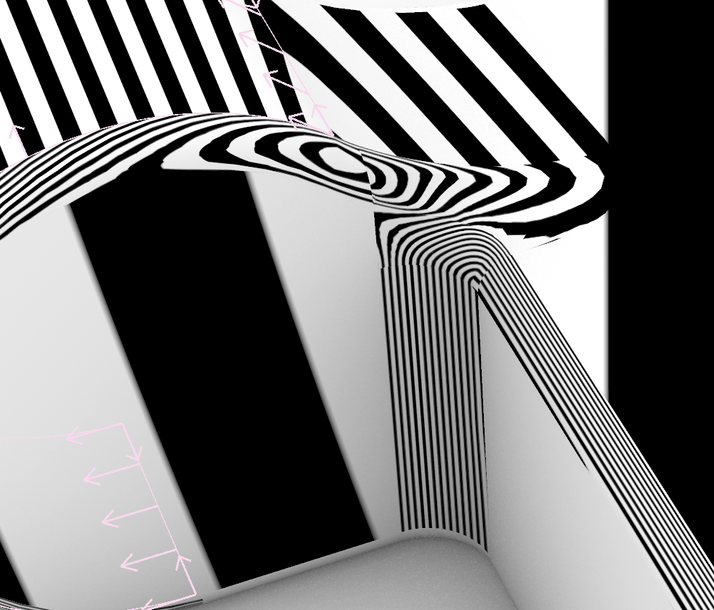
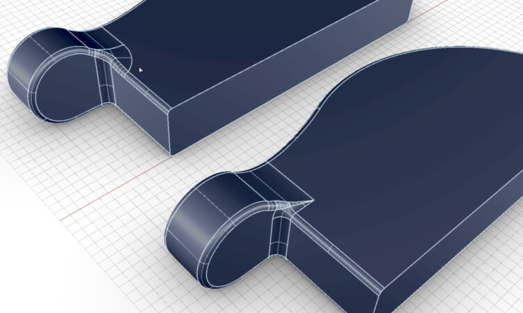
The main goal of my project is to create clean and smooth surfaces while adhering to the fillet radiuses of the reference model I have. I’ve tried almost everything: Sweep2, FilletEdge, pipe trimming, MatchSrf, BlendCrv, NetworkSrf… but nothing seems to work perfectly, and it’s driving me crazy.
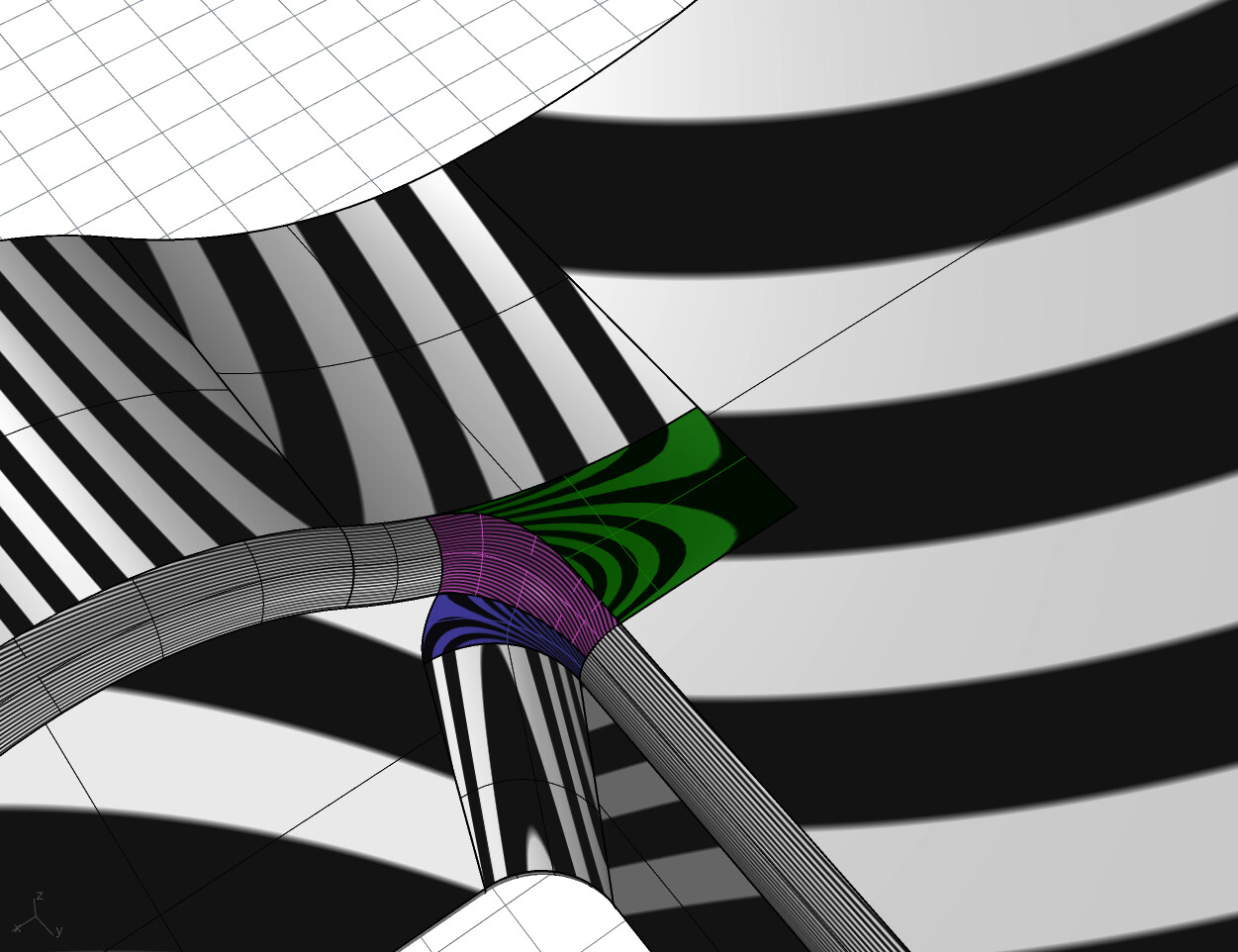
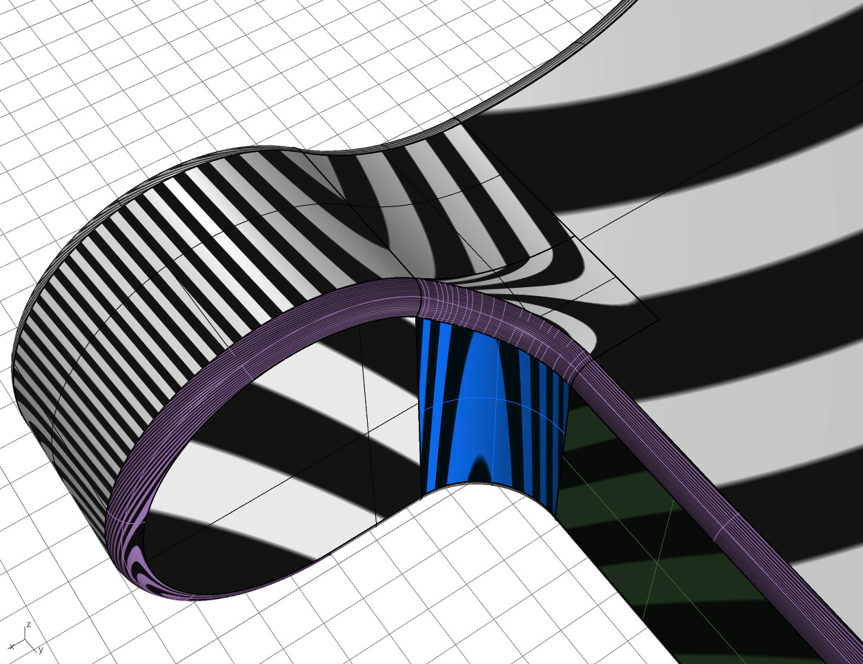
start with the green surface (which is trimmed towards the violet srf)
_extrudeCrv
_changeDegree to 3
_setPt to make the 2 last rows of cvs the same height as the planar big surface
the blueish surface is a simple
_revolve or _filletSrf
the violett srf is initially a _sweep2
set up all crvs to get a nice single span surface.
move the cvs optionally ( i did not fiddle it to perfection…)
_matchSrf …
from a design (er 's) point of view - i would love to see a nice R0.5 edge. (violett)
but this would requier the green surface and blue radius to be adapted.
Thanks a lot for trying; it’s not too bad and certainly better than what I did! To be honest, I was not aware that a v9 work-in-progress was available. I found out about it while I was on the forum. I´ll give it a try.
Thanks a lot man! I definitely have to give the v9 a try.
I will try to apply your method in a couple of hours. I want to be able to do this on my own as well, and it’s really nice from you that you wrote down all steps.
Cheers,
Thank you, at least I had “something” right. I just couldn’t match the whole stuff correctly (G1, G2), although I always blend the curves from extract isocurves or always with Tangency settings… I guess I lack some knowledge there.
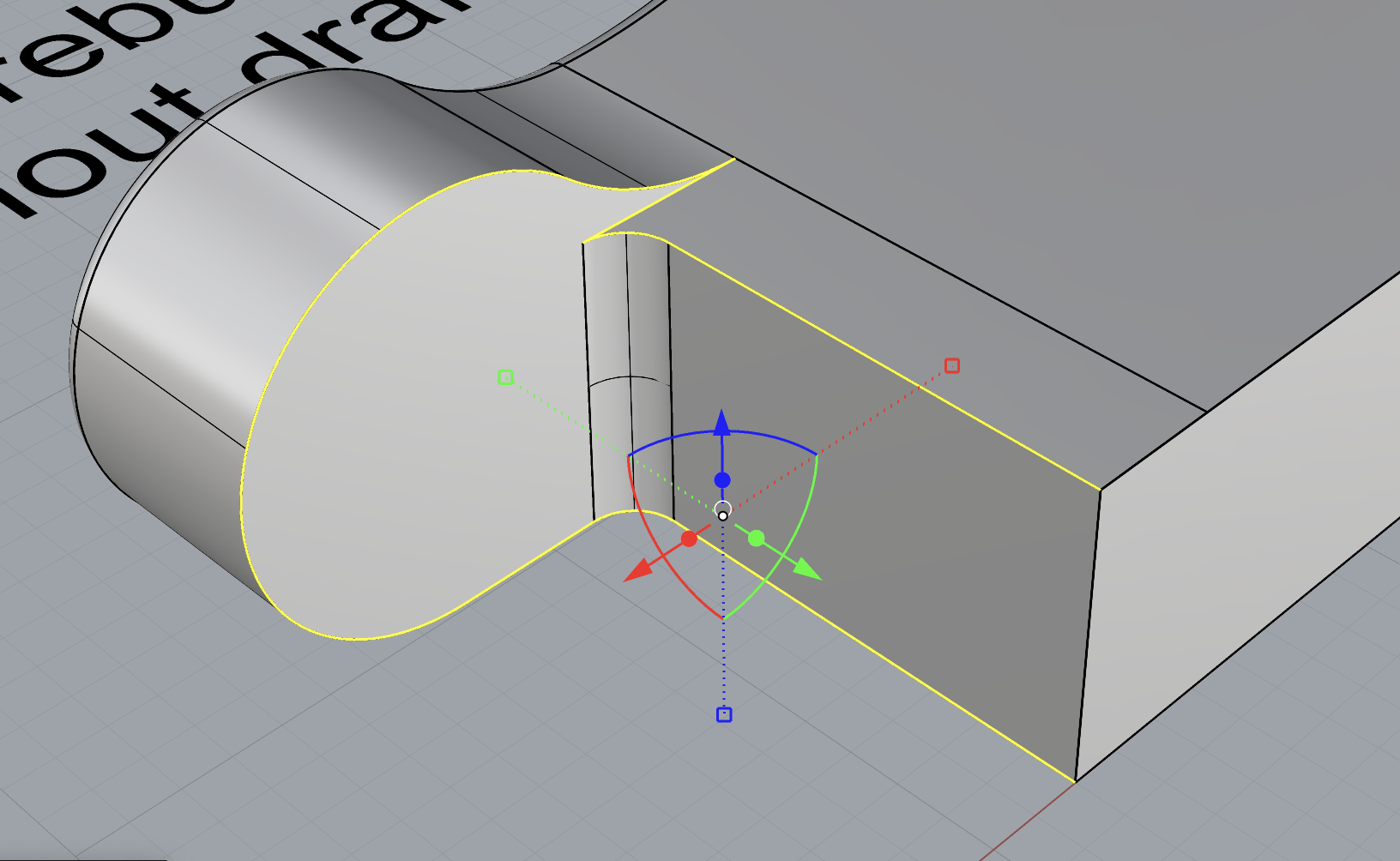
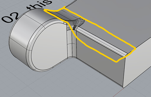
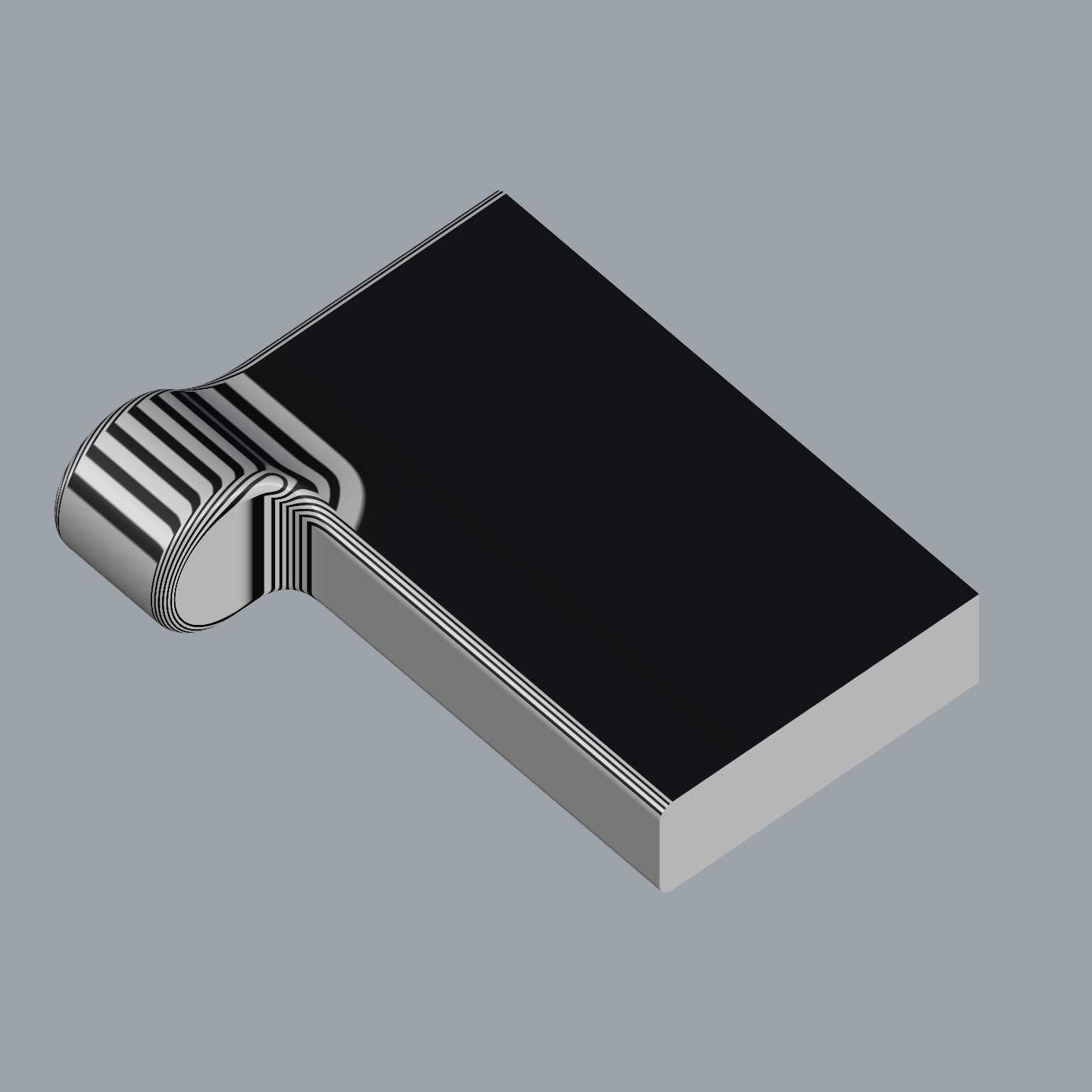
The elephant in the room is that this is a case of “bad modelling”. No cads are great at solving stuff like this, so what you need to do is to simplify the task for the cad.
Here I would have modeled this surface as one (or three) and then you’ll just have one edge to fillet:
@Holo Indeed, when I opened the original file I thought “but why” ? If I had to design it from scratch I would have followed the same approach but actually, the mold is already opened and running. Thanks for your feedback and solution, much appreciated.
@nxakt
Cool approach. I opened your file and I told to myself, yup that’s definitely a good way to go. I rarely touches control points on “complex” junctions, because I am a bit afraid/lazy and expect the software to do the “magic”
I believe the original I get should be after DFM process since the part is being injected for a while.
I also believe they solved this issue for mass production with sand papering the mold or so… just a guess.
@CADARTZ
Agree, I am so happy of all the answers I got. Truly thankful to the community there. Last week ended with headaches and this one begins with a lot of energy.
I can tell you more: our partner models with Solidworks, since they are not a design company but a manufacturing company, they focus on feasibility and getting things done quick to send them into production. I wanted to remodel it for rendering purposes, getting rid on the draft angle edges and so on.