the incredible bobi it’s so beautiful it makes me want to go and try to learn how to build frames tubes and all that goes with it. you should make your own car brand .
1 Like
Thank you for the nice words! I appreciate your opinion! You will definitely find it quite interesting to design tubular frames and suspension. ![]() The challenge with problem solving is what makes me enjoy the end result even more.
The challenge with problem solving is what makes me enjoy the end result even more.
1 Like
a complete and total masterwork-
thanks for sharing!
1 Like

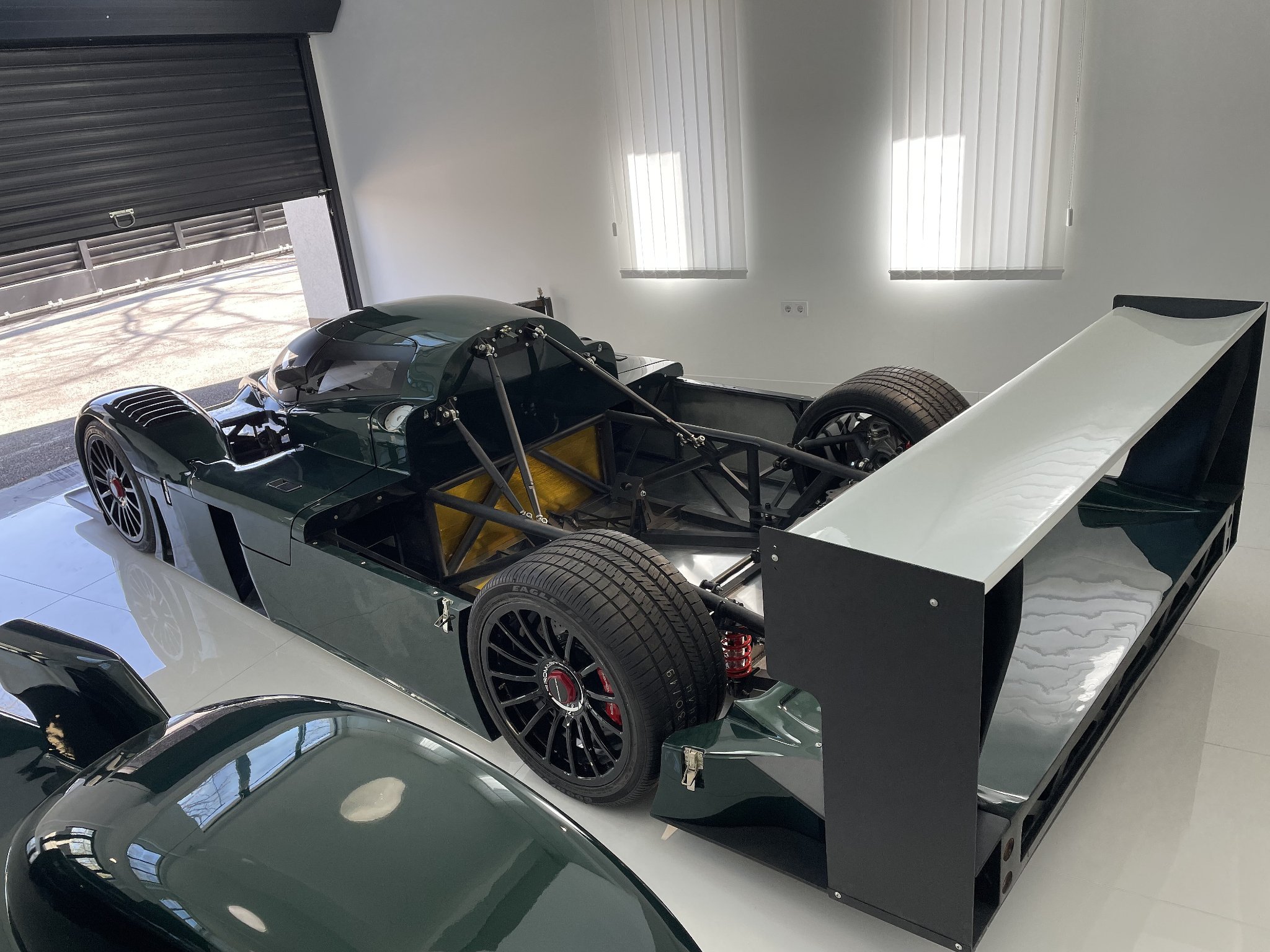
Yet another Aeromaster LMP was built and it got a British green colour and a white livery closely resembling the original 2003 Bentley Speed 8 LMP prototype. ![]()


19 Likes
positively amazing work… thanks for sharing!!
1 Like
Thank you for the appreciation! Another one is being built right now and next month I will be able to show some new Rhino modeling.
1 Like
can’t wait!
18+ ![]()
Various plugs for CNC-milling of the interior panels and exterior panel reinforcements:


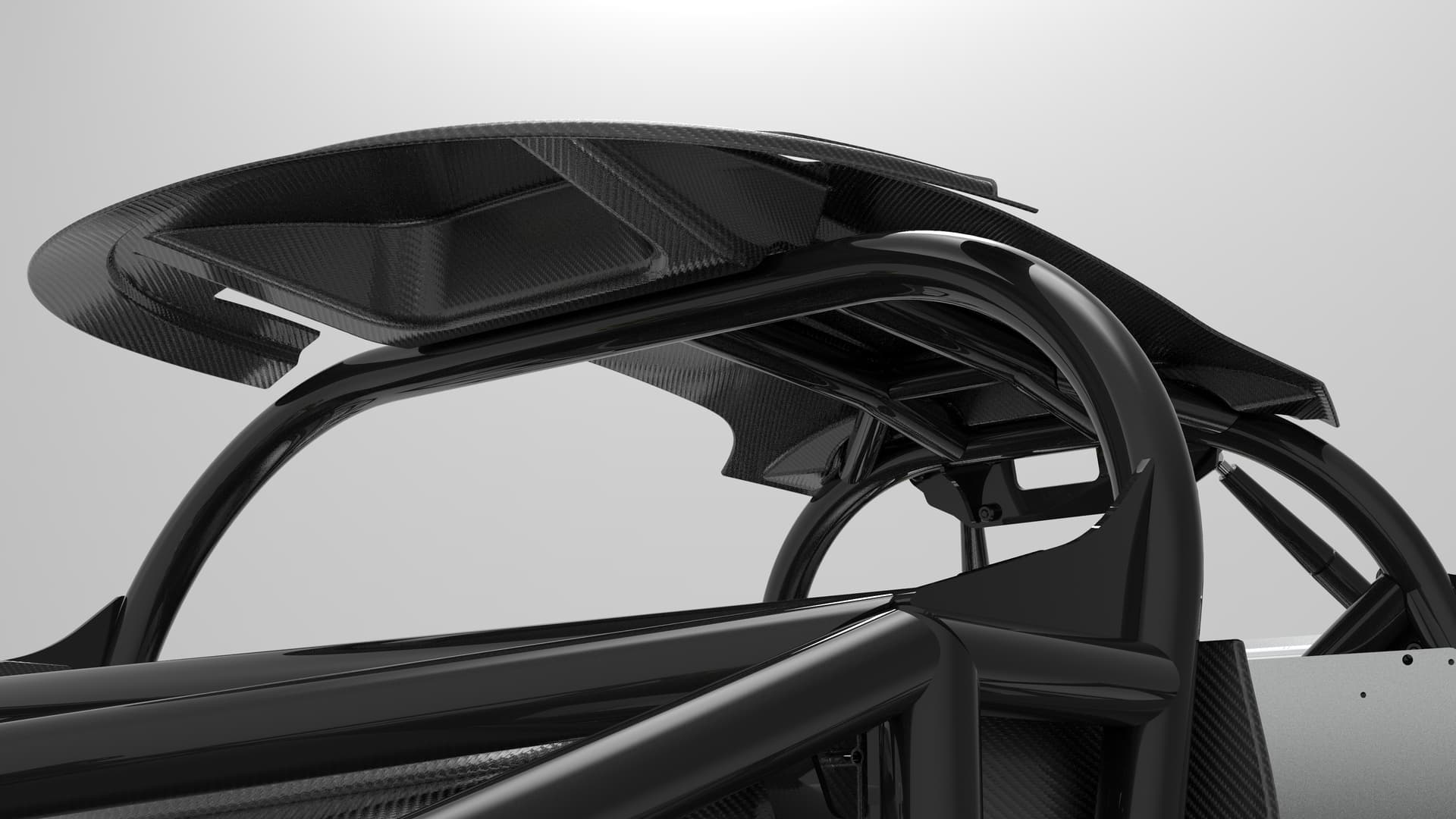
Reinforcements for the engine cover:


Roof mounting panel:


New dashboard and A-pillar covers:


Custom made steering wheel housing and brackets:


The front and rear sub-frames are now made from aluminum to reduce the mass by almost 3 times:


24 Likes
This is insanely cool! Renders me speechless… thanks for sharing!
2 Likes
Thank you for the kind words! It’s a very exciting project and I can’t believe how fast the time flies. I started working on it back in 2007.
2 Likes
such amazing work! thanks for sharing it!!
1 Like
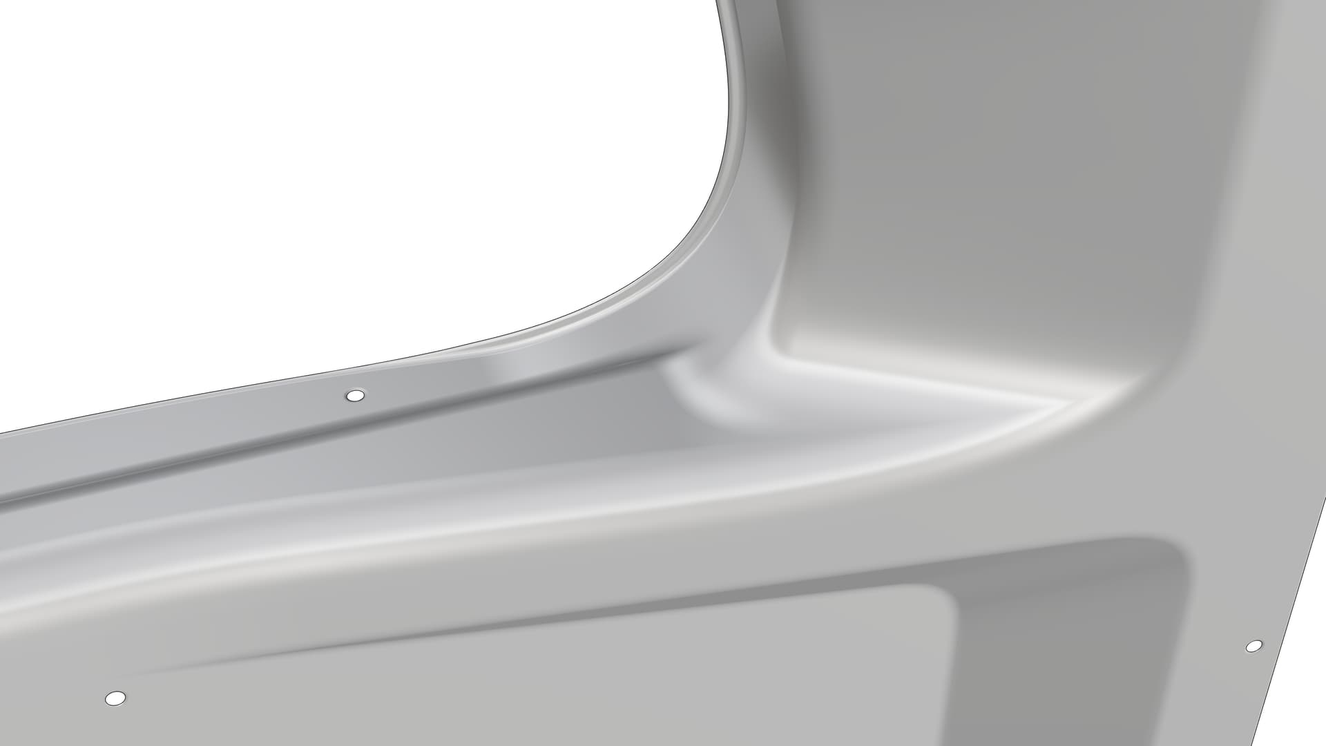
The model shown in this particular example consists some areas with negative draft angle, which usually require a large and expensive 5-axis CNC-milling machine. However, there is an easy solution to achieve that with a basic 3-axis CNC-milling machine, in order to reduce the overall manufacturing cost. It only requires to divide the model into several pieces in a clever way, so that the negative draft angle area (located in the smaller of the three pieces) is CNC-milled from top side and then assembled pointing towards the side. This technique makes it possible to produce such a complex model with nearly any 3-axis CNC-milling machine available on the market.


15 Likes
Pictured below are some of the possible seat positions utilizing a split frame design that offers a good amount of customizability. The adjustment is fully manual and requires removal of the seat itself, as well as 2 (tilt) or 4 (moving up/down and forward/backward) bolts underneath for each position to be changed due to the use of round holes instead of long channels. Channels are avoided for safety reasons.
The removal of the seat is necessary due to the very tight space in the cockpit when two seats are installed together. It would be basically impossible to reach the sides of the seats in a typical configuration with bolts installed from the outside. This is why a decision was made to install the 4 bolts from the inside, located below the seat.
Forward/backward adjustment is done in 3 steps by 25 mm each. Vertical adjustment is 20 mm high. Seat tilt is 4 degrees.


Tilt A:

Tilt B:

Low backward:

Low middle:

Low forward:

High backward:

High middle:

High forward:


14 Likes
bro all the pipes joints and assembly parts purely model in rhino 3d?
thanks
Yes, they are made in Rhino. Once I was happy with the final arrangement of the tubes by drawing simple lines, I used the “Pipe” command to make a round tube along each line. The process is repeated for the inner wall, as well. Where the tubes intersect with each other, I split them via 0,2 mm offset surface of the opposite tube, so that I can have a tiny gap between the tubes. Real-life tubes tend to have some irregular inner wall thickness and they are sometimes not true circles but ellipses, this is where the 0,2 mm gap helps to mitigate those imperfections.
As for the square and rectangular tubes, I simply drew the profile with lines and fillets, then used “Extrude” to make the extrusions in the desired direction.
Here is how I created the drawings for the turned parts:

8 Likes
Your art truly inspires me and a lot of other people.
Rhino is not parametric software, which is something to keep in mind when comparing it to programs like Solid Works, Autodesk inventor, and others.
Did you experience this too?
Accordingly, you may link the connections between parts and change one element to have an impact on another, just like in SolidWorks.
Tell us how you handle the changes.
I appreciate it.
1 Like
While Solidworks and other CAD software are capable to automate the changes of an existing tubular frame, it’s not a huge deal breaker that a Rhino user is forced to re-trim the tube ends manually. That’s just a very small amount of time compared to the overall work needed to design a car chassis. I find Rhino much more user-friendly due to the unmatched camera control and ability to go through extremely narrow spaces, especially while using Lens length of 35 or lesser instead of the default value of 50. Solidworks in comparison performs really bad in this regard. Another advantage of Rhino is the free-form modeling which is mostly not possible in the usual parametric CAD programs. Custom viewport modes also help a lot during the modeling process.
4 Likes
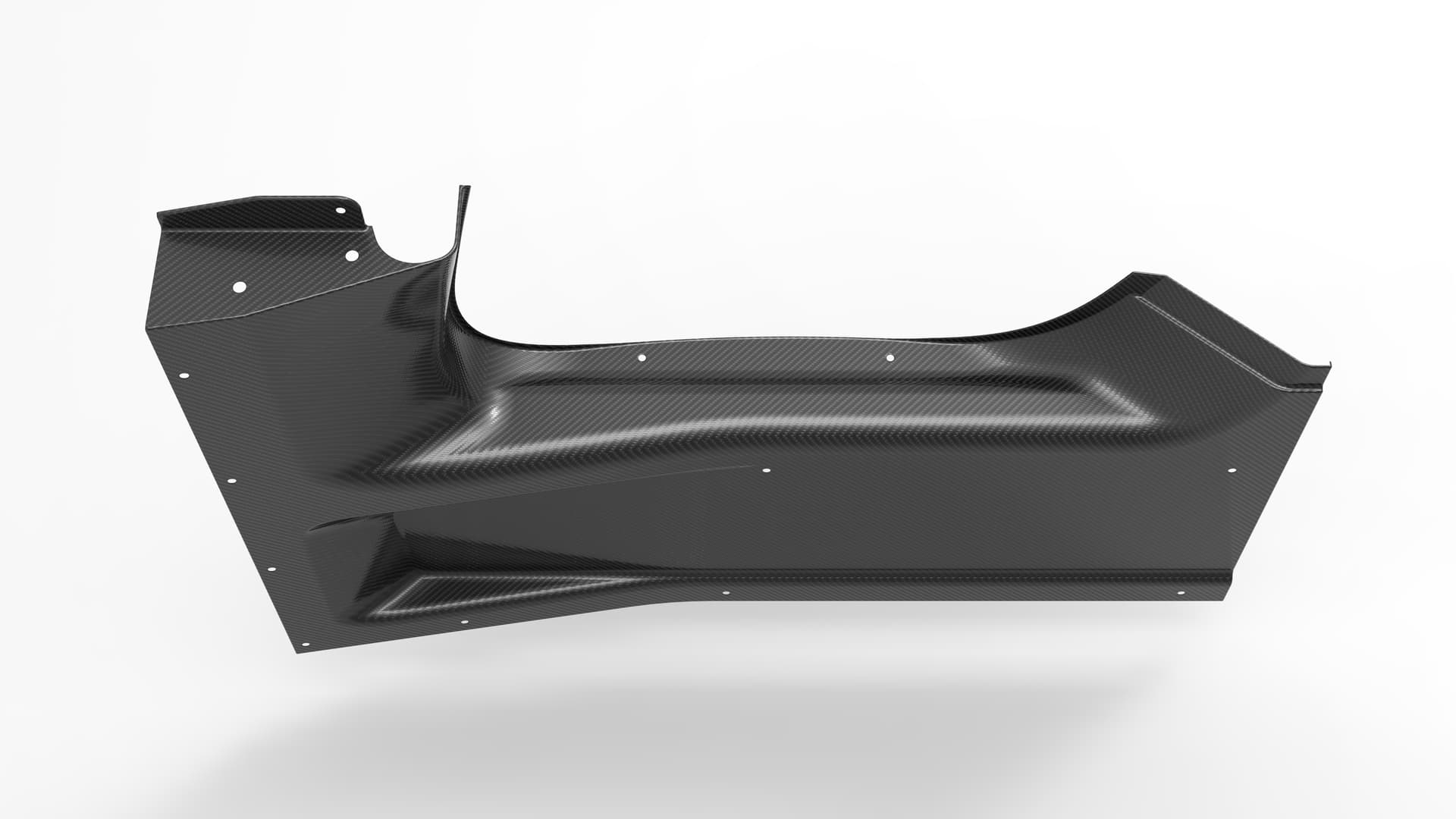
Playing around with some new panels for the Aeromaster LMP. I recorded the full creation of one of those from initial surfacing to making the 3d plug to be exported for CNC-milling.
I did lots of mistakes and obviously some surfaces could have been much better, but that’s the risk of having limited time as other composite parts and chassis modifications are on the waiting list. ![]()


2 Likes
+11111111
1 Like