We are transitioning our workflow from static Plan/ Section views in VisualArq to real-time viewports in layout for documentation.
Our Rhino5 virtual model is built by a collaborative multi member team (3-4 at present) as the real factory fabricated building kitset. It has several hundred individual 3d components organised using blocks into many level nested assemblies and arrays the majority of which we fabricate in-house. Another ancillary use of this model is to generate plans and sections using VisualArq for producing flat paper-based documentation for consultants and regulatory authorities.
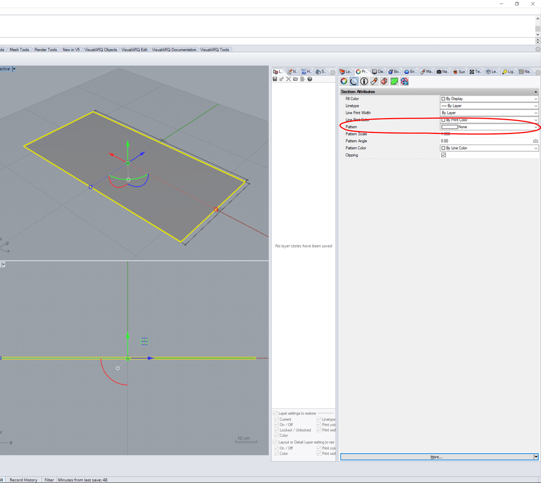
Looking through the forums it seems that to generate hatching and line-weights through cut objects is done by setting up the Section Attribute Properties for each component individually. Having done initial tests we can produce hatches in real-time VA sections either Solid, Single line or Double line but there are no other options for Pattern styles available in this even though there other hatch patterns available in the document - my initial question then is whether it is possible to define further Patterns for cut through components - for example we would like to define a stippled dot pattern when cutting through a sheet material which is a polysurface/ closed extrusion
Hi Danny, it seems like the patterns are not displayed at the Section Attributes Panel until they have been used in the document. We will fix this, but in the meantime you can just draw a hatch “stippled dot pattern”, delete it, and later on you will have it available for the section attributes.
You can see from the attached 3dm file that using Rhino hatch command within a boundary and then adjusting scale/rotation and subsequently base gives the desired effect. When transferring these settings to the Section Properties of the polysurface there is no option to adjust the base setting to achieve proper visual alignment of the pattern.
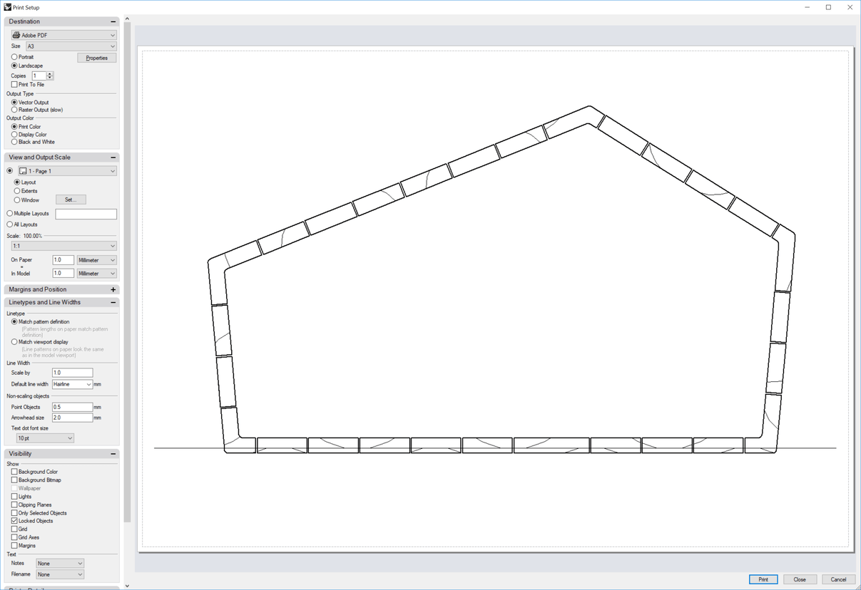
In addition when I set up the section view in a layout the hatch scaling is completely different in both the layout tab and the print setup dialog as shown in the attached images
It is true that it is difficult to place the hatch in the right position. The fact is that it would be too difficult to guess the direction of a polysurface, so the only way to solve this will be to have aligned patterns in the layers of walls, slabs and roofs, which will be available in future versions.
For now I wouldn’t know how to do that apart from dividing the corner element in two parts.
About the scaling in the layout, this is something related to Rhino, go to Options > Hatch:
Ramon,
There could be a linear pattern, or just a line with custom line type (type and scaling). With such a feature there is no need to align a hatch, I hope.
The line could be an option when defining an element.
Cheers, Jaro