In my company, we machine a lot of parts using CNC. Our machinist uses DXF files that we send him from the 3D volume. So we have to create these 2D DXF files (which takes a lot of time) that include all the cutting information (drilling, external cutting, internal cutting, pockets…).
Some time ago I created a python script that works most of the time, but we’d like to recreate it in grasshopper so we can use it directly in our other parametric models.
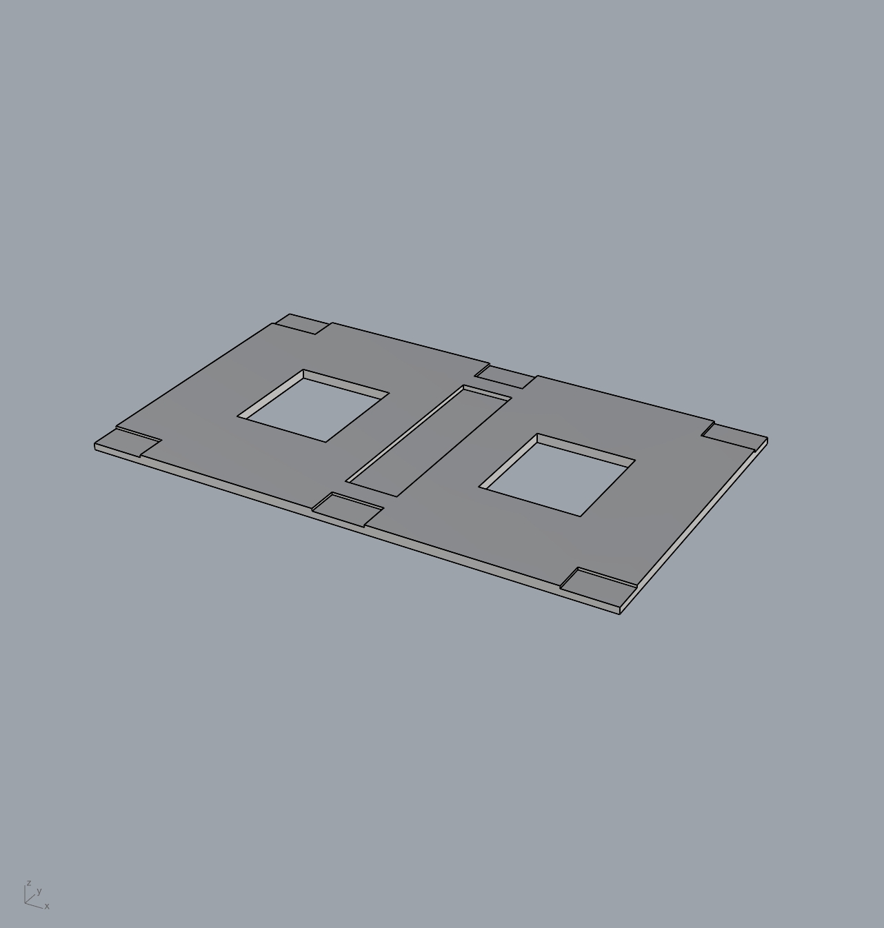
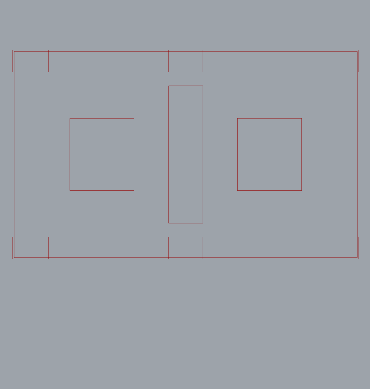
I’m not a grasshopper expert but I spent a few hours trying to create this definition (.gh link below). My aim is, from a part with cut-outs and pockets, to obtain a 2D curve of the underside (which gives me the outer contours + drillings) as well as the 2D curves of my pockets. I don’t need the top face curve (which I tried to do on my gh file). I need the curves to be projected flat on an XY plane.
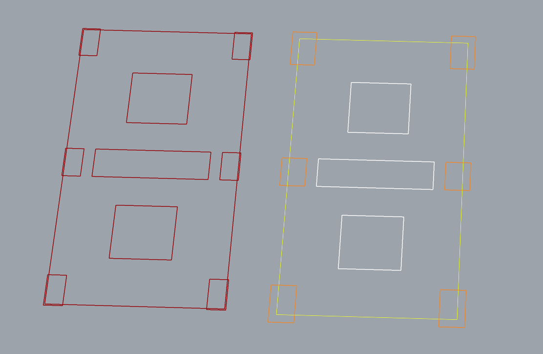
Finally, I’ll need to offset all the pocket curves that overlap with the bottom face curve (image below). I need this small offset so that the router bit machines the pocket a little further than the outer cutout to get a clean finish. I haven’t come close to a solution on this point.
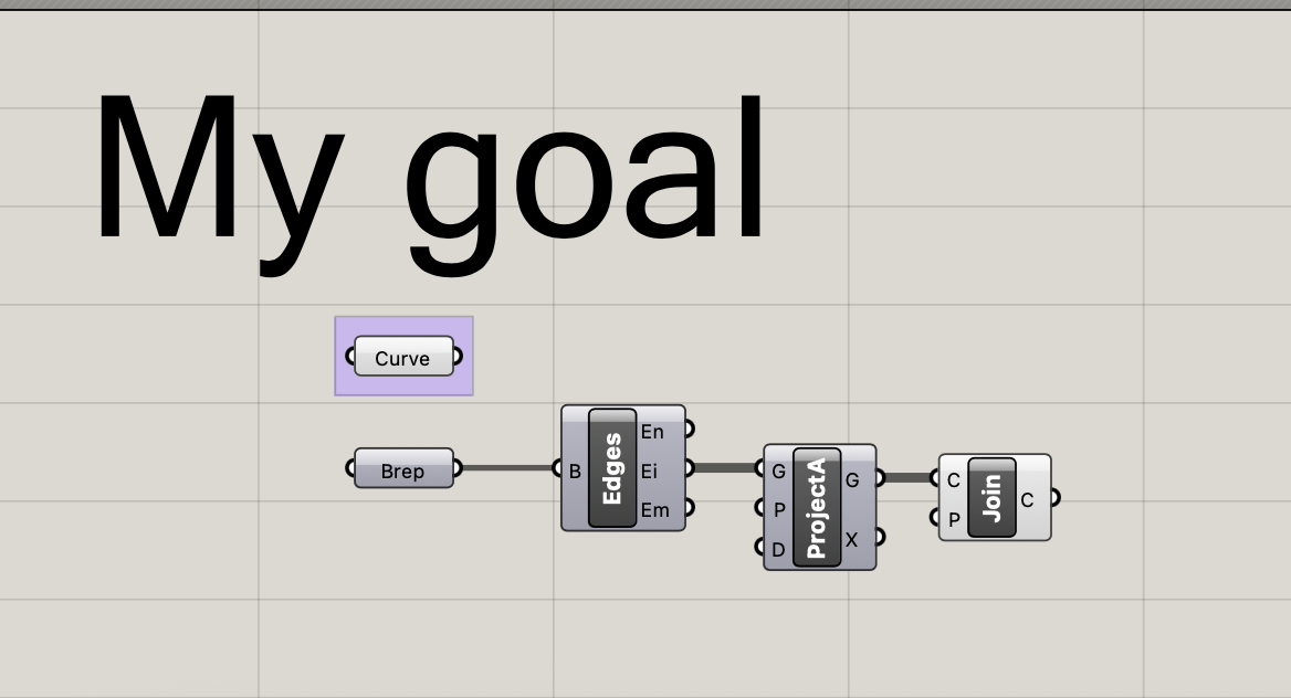
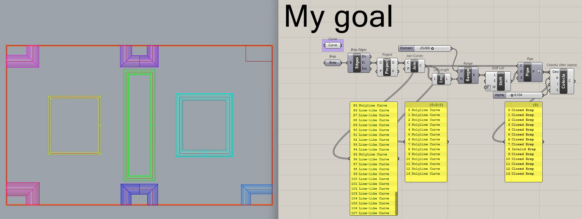
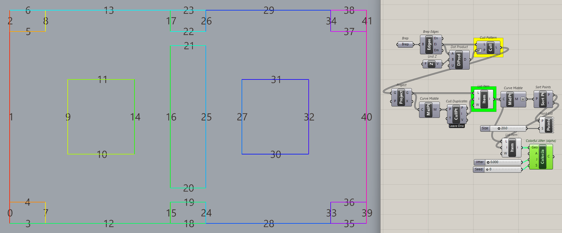
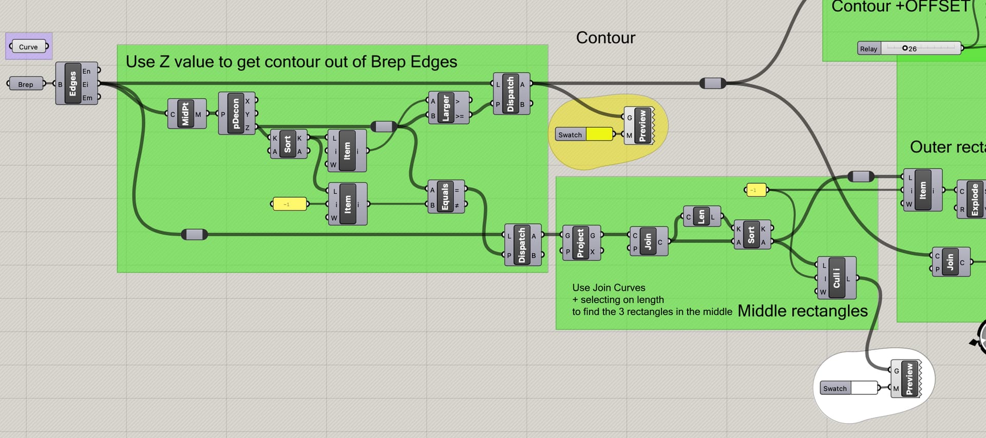
Brep Edges gets all the edges out of your brep. (just as it says )
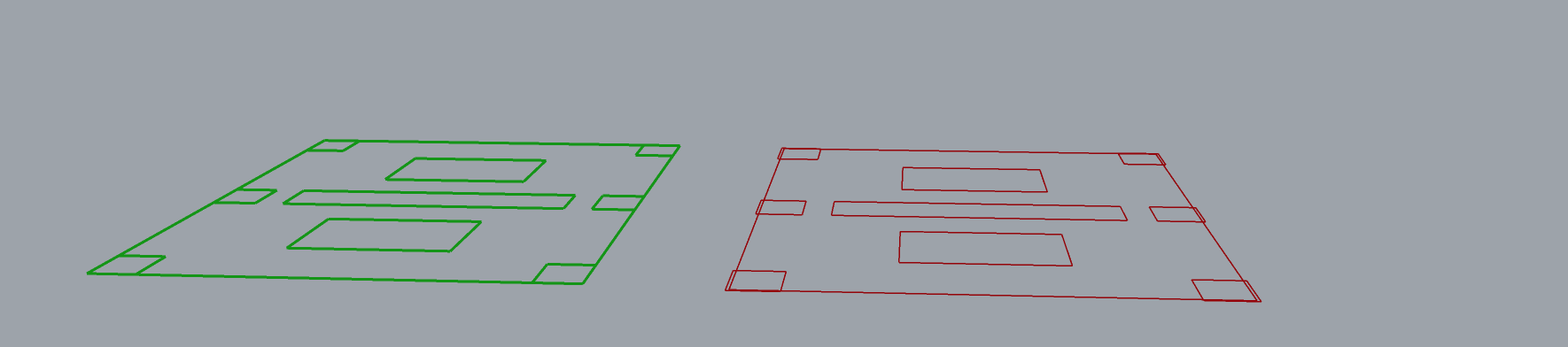
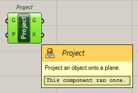
Project these on the XY plane
Erratum:
I did write - Join the curves to get rid of the duplicates.
Is not correct. It is more a cosmetic change. It looks like the duplicates are gone, but as @Joseph_Oster demonstrated, they are still there.
I see three cases here. A boundary pocket, thru pocket and an interior pocket. 2D curves don’t seem incredibly helpful. One can easily check the part to determine the pocket outline and depth of cut. Grasshopper can solve all the math you need and collect that data into whatever format your machine might need.
If you are cutting ferros materials it sounds like you might want better CAM software. Many packages have automatic toolpath creation that would work for a simple part like this. Rhino has an addon.
This sort of manual (or in this case artisanally automated) translation from model to manufacturing is a rather obsolete way of working isn’t it? I only have a hobbiest’s experience using Fusion 360 and VCarve, but I go straight from model to tool paths, with no intermediate 2D step. You could probably save yourself (and your machinist) a lot of time! Some starting points here: Free CNC Software (reputable source!)
More often than not, there are multiple employees involved in these processes and not one who does or even just could do it all. In some cases the process is split into tasks to keep employees busy and charge more as a consequence.
Yes, we use Vcarve most of the time, sometimes fusion360.
You’re absolutely right about that. My company was small 5 years ago, it has grown very quickly (from about 10 people to over 50 today). A lot of people are still used to “ artisanal ” methods and are not familiar with automation processes on a larger scale.
We have a design office that creates the 3D files and a machining office that handles the encoding part. We separate the two to be able to go faster, but it’s far from efficient. If it were up to me, I’d use RhinoCAM or Fusion360, but I just don’t have the time to do it.
We’re currently changing processes to avoid DXF files, but it’s quite complicated to change the habits of dozens of employees at once.
This explains a LOT
10 people can muddle by but 50 people need processes and nobody has the time or inclination to implement them while the whole company is accelerating. Meanwhile the founding employees (who have the most authority to make changes) are settled in their way of working. You have my sympathies, and good luck with your habit-changing program!
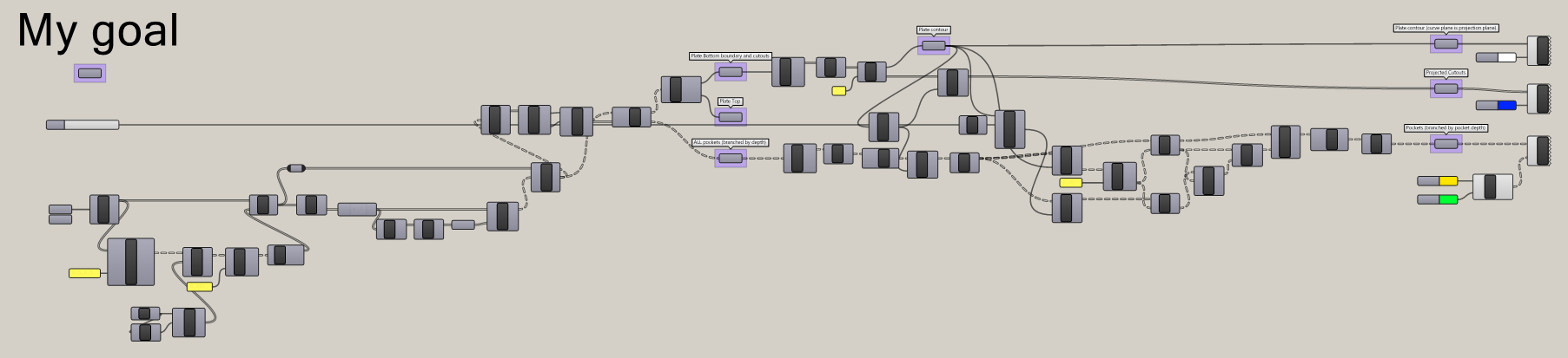
I tried some stuff, not sure how much robust it is… tried to create a custom Brep to test it, looks like it’s working fine, but to be fair it would be much useful if you could supply many of your plates to test different scenarios
I specifically developed KaroroCAM to replace Fusion360 in my own work flow and remove the export/import time suck that using Fusion for CAM added to my day.
I’d be more than happy to give you a trial license and work with you to setup test tool paths to see if this may be a suitable route for you/your business.
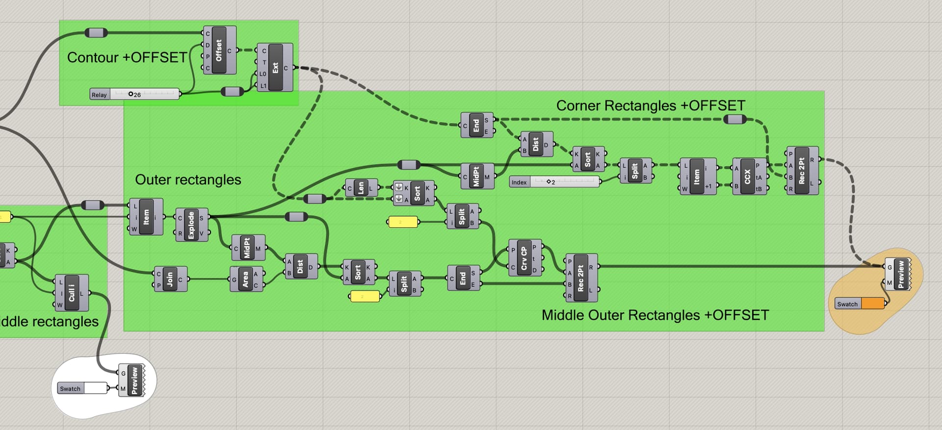
get Z values, lengths, distances to “anchor points” you choose
then test/compare and select what you need.
A bit depending on how close next project of you are, it could be more automated (replace sliders with logic). But I think the approach is rather clear and easy to use as a starters for coming projects.
I’ve just tested your definition on several of our parts, there are sometimes a couple of errors. I’m going to collect several pieces and share them here.
On our simplest pieces it seems to work very well though! It’ll save us time already.
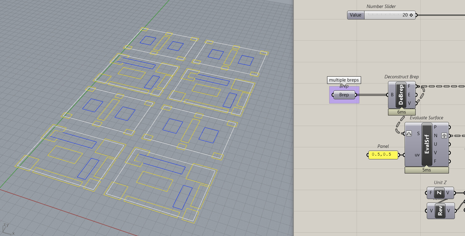
I’m wondering: do you think it would be possible to set multiple Breps instead of just one?
yes for sure, but not in the state it currently is because I didn’t really put efforts and I violated all the rules of building a good definition that was just a dirty sketch
if you collect many samples for which it fails, it would be much useful data
[edit] @brice1 this version works (only) on multiple Breps (nothing else changed: it will still fail where the one-brep version was already failing)