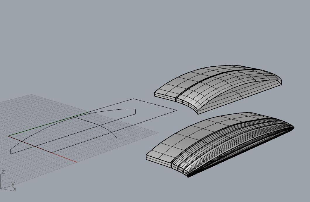
Well, I basically looked at the sketch of those profiles, and also the images you provided; then I made some educated guesses on what I know in my experience working from napkin sketches and paper templates for fabricating different materials n’ such.
All I can say is in my perspective, those sketch profiles look more like a guide for what the fabrication process began with. Then over time the process may have changed and even may have been reiterated.
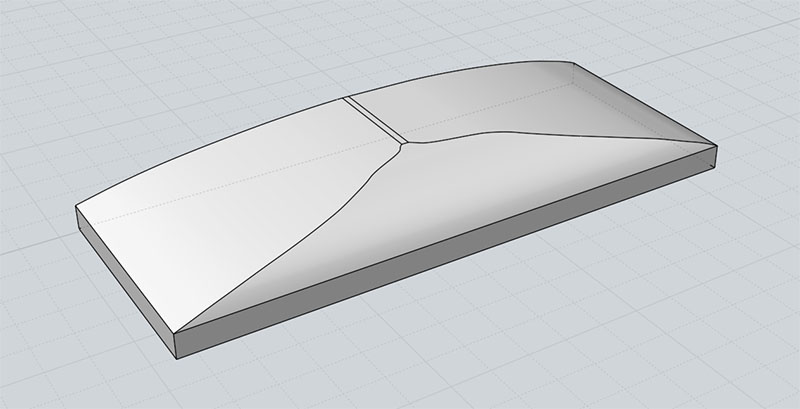
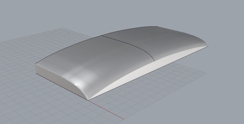
So, looking at the images and trying to ignore the optical illusions of the lighting and the shadows, I’ve surmised that the front and back of the component believed to be in question; appears to be rectangular on each end – so I basically added for/aft profiles at an approximate height relative to the sketch profiles at one particular corner.
Then, the main difficulty is deciding where in between those main two profiles should reside.
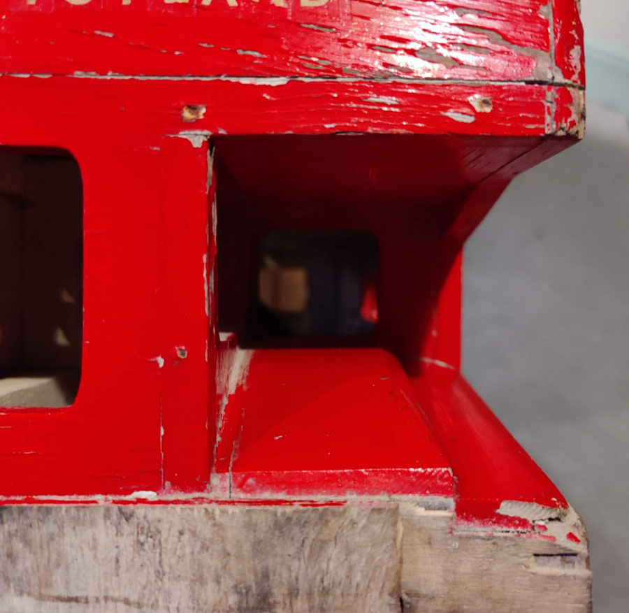
Notice in this image how it’s not perfectly 12mm. Hence, the “maximum height” should be 12mm +/- how much? 12mm +0.000? and -0.000? 
I’d say that the ‘hand-work’ should always be treated as the correct shape, but it all depends on the ‘design intent’, and where it leads.
Most likely the ‘design intent’ can evolve over time throughout the hand-work process. And ultimately, it all boils down to what the ‘precision’ constraints are.
Of course it’s always really good to have original design profiles, but hard to say how that intent may have evolved over time during each stage in the process.
So, without ‘plans’ that get more specific, there’s merely countless numbers of ‘degrees of freedom’ for the ‘design intent’ to change over time throughout any process.
And, there’s pros and cons to anything really – sometimes pure freedom is good for development, but not good for mass production, per say.
If you want more than one of something or even something with ‘symmetry’ then some ‘constraints’ or rules need to be established to within a certain ‘tolerance’.
So, if I were to reverse engineer that shape for example, I’d be asking specific questions like Length, Width, Height +/-(significant figure units) etc.
And for ‘organic’ (compound curvature hand-work geometry) I’d probably try to get as many dimensions as possible – even as much as 250k measurements per square inch, for example.
But without really sophisticated 3D scanners, you can probably use about a dozen photos or so with certain lighting and texture, to then generate a 3D model of said component with an estimated mesh that is accurate to maybe 10k measurements per square inch… I’m just guessing though.
3D scanners have alot of evolution they need to do – they’re still not very accurate relative to price cost. So, I can’t really say you could scan it to +/-0.0025" without a $25k scanner and some skills – for example.
Some day we should all be able to do that for like $200 I bet – only a matter of time. The last 15 years has been rough though, in terms of that technology development.
That company Ametek currently controls some of the best tech since they acquired Creaform.
Another big one is 3DSystems acquisition of Rapidform.