Hi,
V5
Great video by McNeel on V5 modelling a screw thread. well spoken, no errs and umms unlike youtubers, all meat, and in my english.
This would be for zero tolerance though.
Mine needs a traditional V profile.
Having followed this method, is it sufficient to move it as he does but then instead of immediate BooleanDifference, to offsetSrf then Boolean difference the item in part 2 (the female part) from a solid to create a working thread for perhaps 3D printing in plastic or metal and what would the tolerance gap (OffsetSrf) need to be on 1.4 inch diameter item with pitch 0.14 inch ?
Filleting the V as he has done would seem tidy also.,before the above mentioned OffsetSrf is done.
I guess the question is how is the model going to be made physically? Will it be printed or machined?
if so, make them at zero tolerance and run a tap into the threads as a post process. It’ll clean them up easily, and the screws will thread into them perfectly.
Hi, V5
It would be great to just grab the male thread and offset, rather than have to contrstruct all over again, but if thats what it needs.
I will have to offset outwards the tunnel for the shaft, then offset outwards the profile, then helix it etc etc.
How is that better than offsetSrf I wonder, always willing to learn.
Thanks Kyle, its probably to be 3D printed, minimal cost, and doesnt exist off the shelf or as a Mcmaster Carr product, unless they have whitworth of the size I mentioned ? Its an item that is unique in form and function.
However, anyone know what the offset amount should be for tolerance please ?
see post 1 on size of it. 3D printing would I presume be ABS unless metal is affordable, though it needs securing to a wooden disc VERY STRONGLY so not sure quite how, maybe a flange and screws where the weld would have been then filler over that for a weld effect.
Steve needs thread systems historically used in the UK which are not included in BoltGen. These thread systems include Whitworth (BSW), British Standard Fine (BSF) and British Association (BA). British Standard Whitworth - Wikipedia
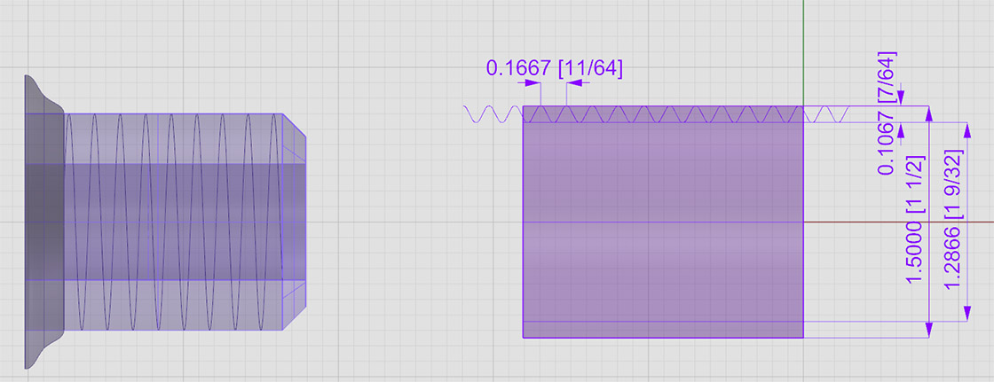
I have now established the boss was a 1.5inch dia (Major Diameter) Whitworth. (BSW)
I have now created the thread profile.
How would I use that to create the thread as the video method may not apply, there may be a far quicker way as I have the fillets etc all in this profile I have drawn after finding a whitworth diagram and data chart.
I need to feather the thread into the shaft at the chamfer end, there would no doubt be a correct transition route for that unlike the video which swings it in by hand, unless that did folow the correct route, for what I have as long as it functions, then ok, but is there a correct swing in route/method ?
attached the essentials ready to go.
see my original bung with incorrect shaft diameter and the new 1.5 dia outer and marked ‘D min’ lines for the valley bottoms. then when done I chamfer the end as before.
I could sweep1 to a helix, just wondering about that feather in at both ends., and before chamfer starts. no real need at weld end, assume sawn off !
Then I hollow out the middle.
Anyone care to have a dabble ?
what is best method ?
It will be interesting to see how its done with genuine thread profiles.
The run-out is done by control point editing of the beginning/end of the helix before you sweep (in a view perpendicular to the screw axis). Run-out is generally only necessary at the end away from the thread start, like when the thread comes up under the head or you have a partially-threaded bolt.
The run-out is maybe not necessary in your case as you specify “sawed-off” at the upper end. Typically there is some run-out there as it’s virtually impossible to mechanically cut a thread 100% up to a shoulder, but for your purposes it may not matter.
No. The lower (chamfered) end does not need (should not have) any run-out, the chamfer covers the lead-in. If you were to put any run-out on that end of the thread, you would not be able to screw the bolt into the nut. Just make sure the helix extends below the screw end (I always suggest one extra turn) so you are sure when you subtract that it gives you a complete cut.
Hi, I am stuck.
No videos at all on how to do a thread with genuine profile whitworth,
I see that McNeel vid where he pulls the thread into the bolt. I see a japanese vid with Japanese music where he has chamfer on inner D min solid (solid out as far as valley bottoms) , and again seems to have swept the end of the helix inwards.
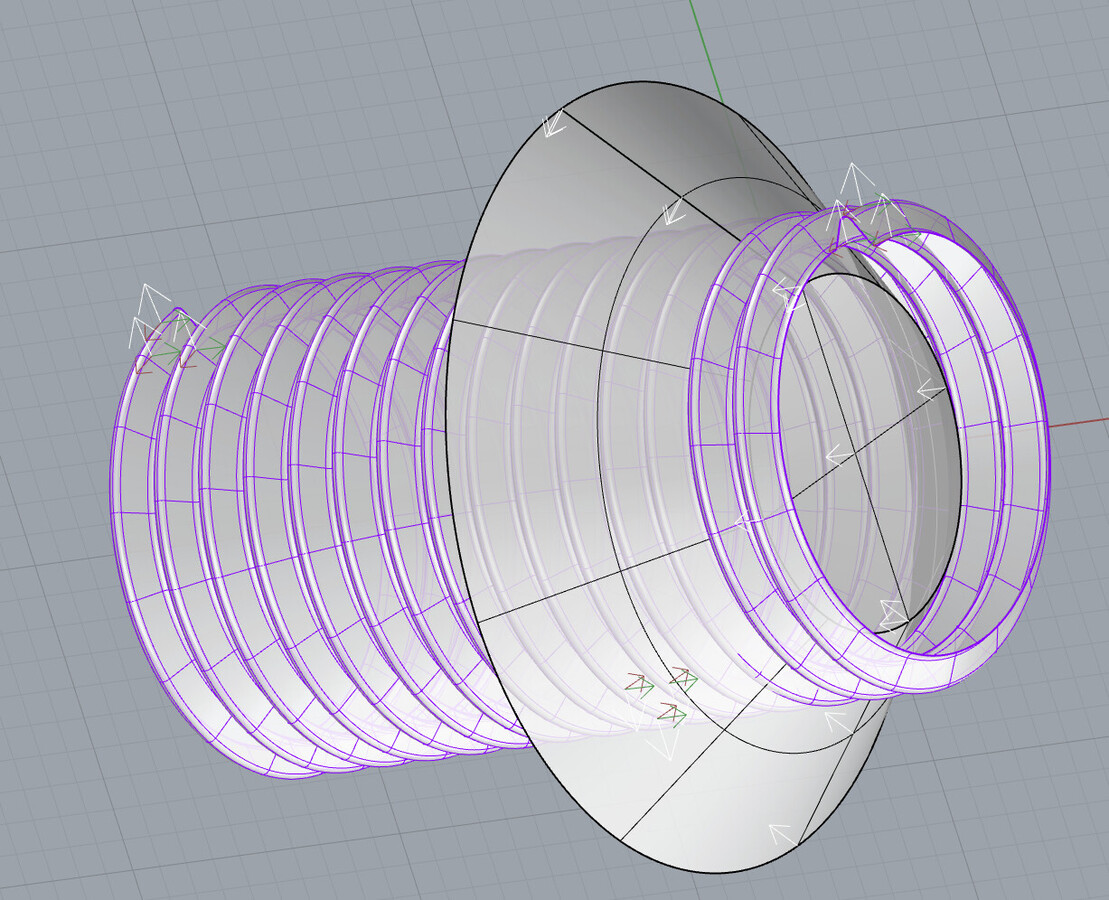
I have a helix and an accurate profile which makes the thread completely, unlike these videos.
You say I need to slice the end at 45 deg, should I create a cone of 45deg and do so then surface the gap on the end ?
I firstly try for a chamfer on the outer solid cylinder but with naked edges I cant even try for that. Whitworth 1.5inch.3dm (1.8 MB)
Hello - Run DivideAlongCreases > SplitAtTangents=Yes, then Explode and Join the threads - that should get rid of the nakeds. Then get a cutter oriented like so:
Great, must look into what that command does (it also had kinks=yes and I left that as is not knowing if it made a difference but it worked so guess that was ok)
I created that blunt end cone as per the blunt end and angle on my helixed one, I didnt think Boolean Difference worked except on solids but it did, so something else learned.
What I wonder about is the sharp edges of the thread at tip, should they be filleted ?
Maybe, I think , they are my position of cone, but as the helix thread is a repeating form, I dont think there is a right or wrong position to place it, am I right ?
The McNeel vid had the tutor placing it to suit his swept in thread but I dont have such so I dont think location of cone counts as long as the thread goes out beyond it.
I made a cut with C4 and another with C5, two cones 0.05inch different on x, layers for each in the layer palette. No obvious difference.
So, if the sharp edges are unavoidable, should they be filleted ?
making a TRUE shape with true profiles has been very rewarding.
Now to follow the table that says thread height female thread.1067 but wait…thats what the male thread is , so not sure on that !
There should not be any naked edges.
To accurately feather the end you can extend the curve which will result in a 3 point curve. If you now pull in the endpoint the pitch of the curve will not change.
This video shows how it can be done. https://youtu.be/OhiMd8nfOKc
It also shows how to model a custom thread, or rather the airgap between the screw and nut, from any profile using railrevolve instead of the sweep command.
The offset on my 3D printed spindles is 0.25-0.6mm, depending on the printer and the filament used.
Here I use 0.6mm on the nut printed in full and 0.25 on the one printed in halves.
If you cut recess/groove in the thread you can hide the z-seam there and it won`t need any cleanup after printing.
Sorry for dragging up the old topic but I thought I would share the video to help others looking for help. I just made it to remind myself how it works…
")