I think that “Match surface” could be a lot better if the following upgrades are made:
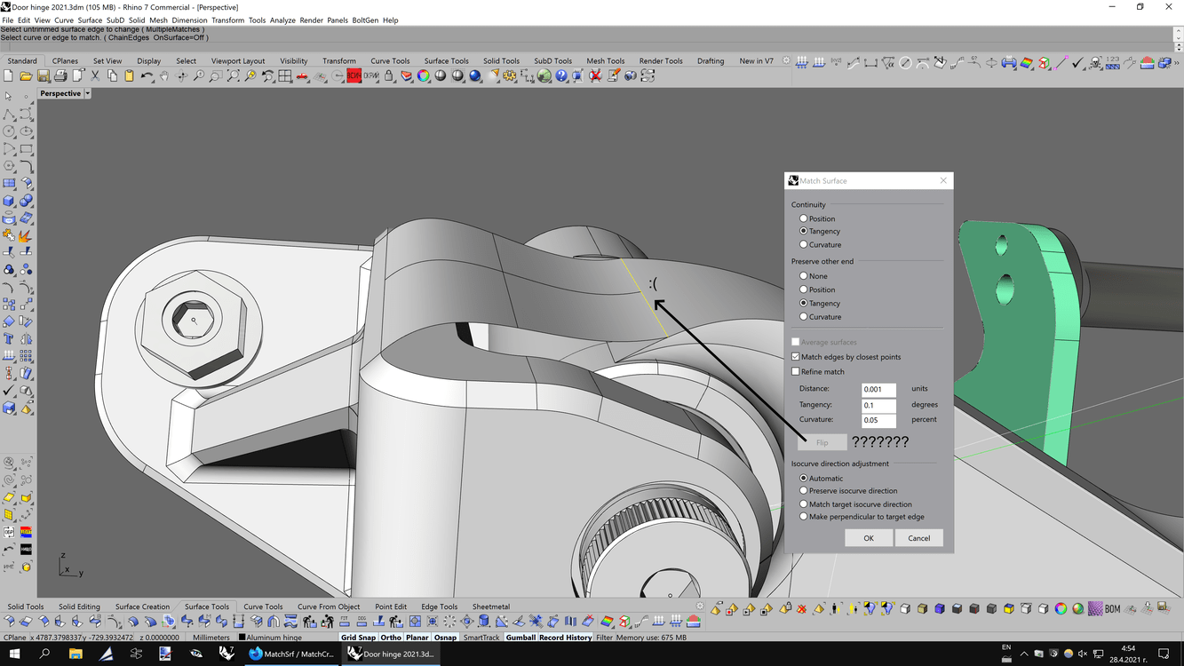
Ability to flip the direction of the matched surface at any given time during the command. Check the screen-shot below. The “Flip” option is not active during matching a surface. Being able to flip the direction is essential in certain situations.
Add a tickbox that activates a “Draft angle” match that the user could control with numerical input or directly in the viewport.
Add a tickbox “Normal to surface” (with ability to flip it if necessary, as per wish 1), which is basically same as a 90-degree draft angle.
Add a new option called “Match end direction”, which will force the surface to be matched to follow the same direction as the target surface (even if the latter is split). It must be also possible to pick an isocurve or curve on surface as an input for the direction. I already proposed that about couple of years ago in another thread. Here is a quick example:
This is a video example for a slow manual workaround that I made recently. I think that both, “Match surface” and “Blend surface” should be able to align the direction of their sides to the sides of the target surface(s):
Here we go again! Best of luck on your, what is it, third or fourth attempt? I’m all for it, but sadly, not many more seem to be (even if they should… and I bet they would, if they could).
I may be wrong, but the main “problem” is that the developers of Rhino probably don’t do full-time modeling work (sometimes I see wrong modeling techniques in official Rhino tutorial videos) on projects, thus they don’t see a reason for some tools or tool features to exist. The good thing is that “McNeel” made this forum and actively listens to people like us, who are doing full-time modeling work for living, and fortunately they really implement some of our requested features in future releases of Rhino. I really want Rhino to become better and this is why sometimes I try to offer some new suggestions for improvements. These are usually a result of facing modeling challenges during work whose solution does not exist yet in the Rhino toolset.
RH-30555 MatchSrf - allow some modifications within the command RH-33627 add end buldge sliders to match srf tool. RH-32304 Some suggestions to enhance the MatchSrf in Rhino 6 RH-5530 Sliders for MatchSrf & MatchCurve RH-46290 MatchSrf - Show the points in the preview RH-55751 MatchSrf: Report deviation RH-58712 MatchSrf : maintain the control point flow RH-54557 MatchSrf: Flip button
Wow, https://mcneel.myjetbrains.com/youtrack/issue/RH-5530 is 8 year old suggestion and still waiting? That same functionality is already part of the “Blend surface” tool, so I suppose that it should be fairly easy to transfer it in a similar way to “Match surface”, too. Or maybe there are some technical challenges that makes this too slow to develop?
Also, deviation while using “Match surface” is automatic on some other programs. Alias, for example, could show the deviation in real time while using the majority of its editing and surface creation tools.
Ability to insert new control point rows where necessary is also critical for the quality of the matching. The “Refine match” options are good, but they are based on tolerance settings rather than user-set total number of control points or position of the newly added control points. The “Explicit control” of Alias is basically like Rhino’s “Rebuild surface” or “Rebuild surface UV” integrated into “Match surface” and “Blend surface”, and allow to change the topology of the surface on the go.
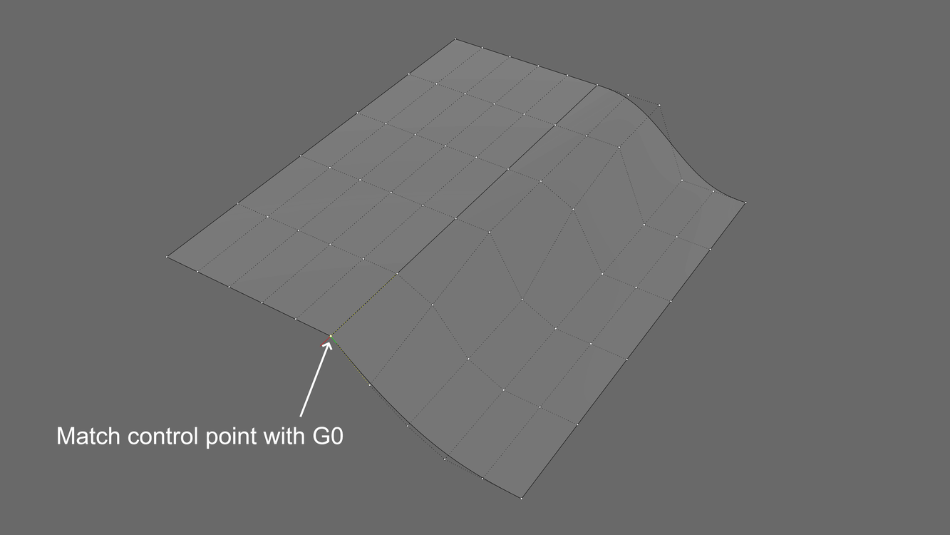
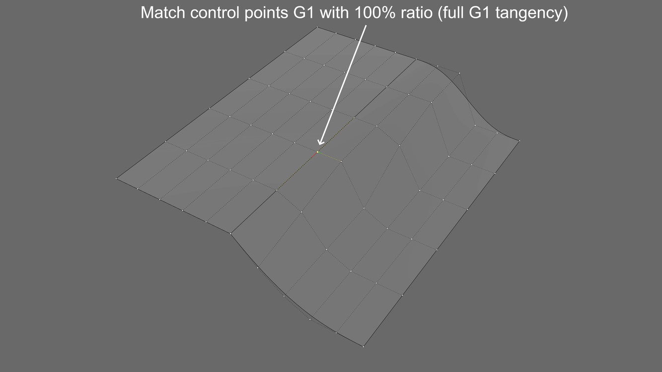
Another mega important wish: Allow “Match surface” to affect only the selected control point row(s). For example, if you select only one end control point of the surface to be matched, only its control point row will be affected by the “Match surface” command whereas the rest control points along the same edge will remain unchanged. You can call that command “Match control point” and assign alias “Matchcp” to it.
This is especially useful for occasions where the intent is to preserve some of the control points and the user wants to change a specific region of the edge only.
Another good use of this technique is where crease lines are needed, so that the surface edge could start with a visible crease, while its end becomes either G1 or G2 to the adjacent surface(s).
Hi, I would add another interesting option, that I use in some cases, which is to match a patch projecting the control points in a specific direction(X, Y, Z) , for example in Y, for patches of the wheel arch or bodyside. In X direction for the front grill…
The benefit of that, is you can mantain a good control point distribution of the patches from that specific view in the same time you are modifying or tweaking them.
If it is too complex to add this feature, just add view projection option(current view) and it would work aswell, and more simple.
I think that the majority of the automotive modelers see my point, cause I use this quite a lot in others 3d softwares.
Thank you in advance.
That’s also a welcomed improvement. It have been requested multiple times over the years. Here is one of my posts where I linked a video example of how the projected match works in Alias:
And here is the same video for a quick overview (after the 9:10 minute is where it gets really interesting):
Here is another case where the projected match could be essential, but this time I will give you an example with matching a surface edge to a curve consisting a different number of control points with some random distribution. Having a “Set direction” option would let the user set a vector for the matching direction in a similar fashion like the “Planar sections” option of the “Blend surface” tool. I think that it’s self-explanatory why that option would make the modeling experience with Rhino so much better. The current implementation of “Match surface” is quite limited and fails to achieve the necessary result, as shown in my video below. By the end of the video I show how that option is supposed to work by preserving the target direction.
Note: If the target curve is longer or shorter than the edge to be matched, then the latter should still try to keep the same parallel direction, even though that may lead to some weird looking results. But when the target curve is relatively same shape and length as the edge to be match, that option would work perfectly fine.
+1 for point alignment…
I would have liked _matchsrf to keep the points visible during the action and to allow you to play with the points to correct their directions and distributions and their distance from the edge. point by point or by row.
(currently it is possible to use the history to work around this problem.) but you have to quit the command before you can make the changes.
view that the history in rhino is limited to these days. I hope it improves in the future in ways that allow real-time editing for both surfaces at the same time. I saw video vsr it has this possibility. if i remember correctly
the big ogre that strangles me is not being able to convert the direction of the third row of points which corresponds to the curvature with a .lock unlock option. to slide the points in the direction parallel to the edge, with the possibility of loosening or tightening the margin of the slide using a slider for example.
even if that does not give a perfect continuity g2 here allows to preserve at least the silhouette of the surface and to be able to modify it as he sees the user.
currently the command makes the third row of dots follow the direction of the second row. which destroys the shape of the surface.
I’m sure this has all been mentioned several times in other threads. not to mention this discussion
Yes, one of the hugely missing functionalities of “Match surface” is the ability to preserve the control point flow while matching with G2 curvature. That must be an option with a tickbox that could be activated or deactivated at any time during the command. The fact that the 3rd row of control points moves along the UV direction is often disturbing and destroys the intended shape of the surface. Activating that option while matching with G2 should affect the 3rd row of control points only in the normal direction, even at the cost of losing some accuracy (i.e. G1,8 instead of a perfect G2). I proposed that approach years ago in multiple threads and sadly it’s still not implemented. I’m pretty sure that many Rhino users would love to use it.
Also, Class-A modeling programs such like Alias benefit from having “Explicit control” over the structure of the surface in the majority of tools, which is basically ability to use “Rebuild surface” inside another active command such like “Match surface”, “Blend surface”, “Sweep 2 rails” etc.
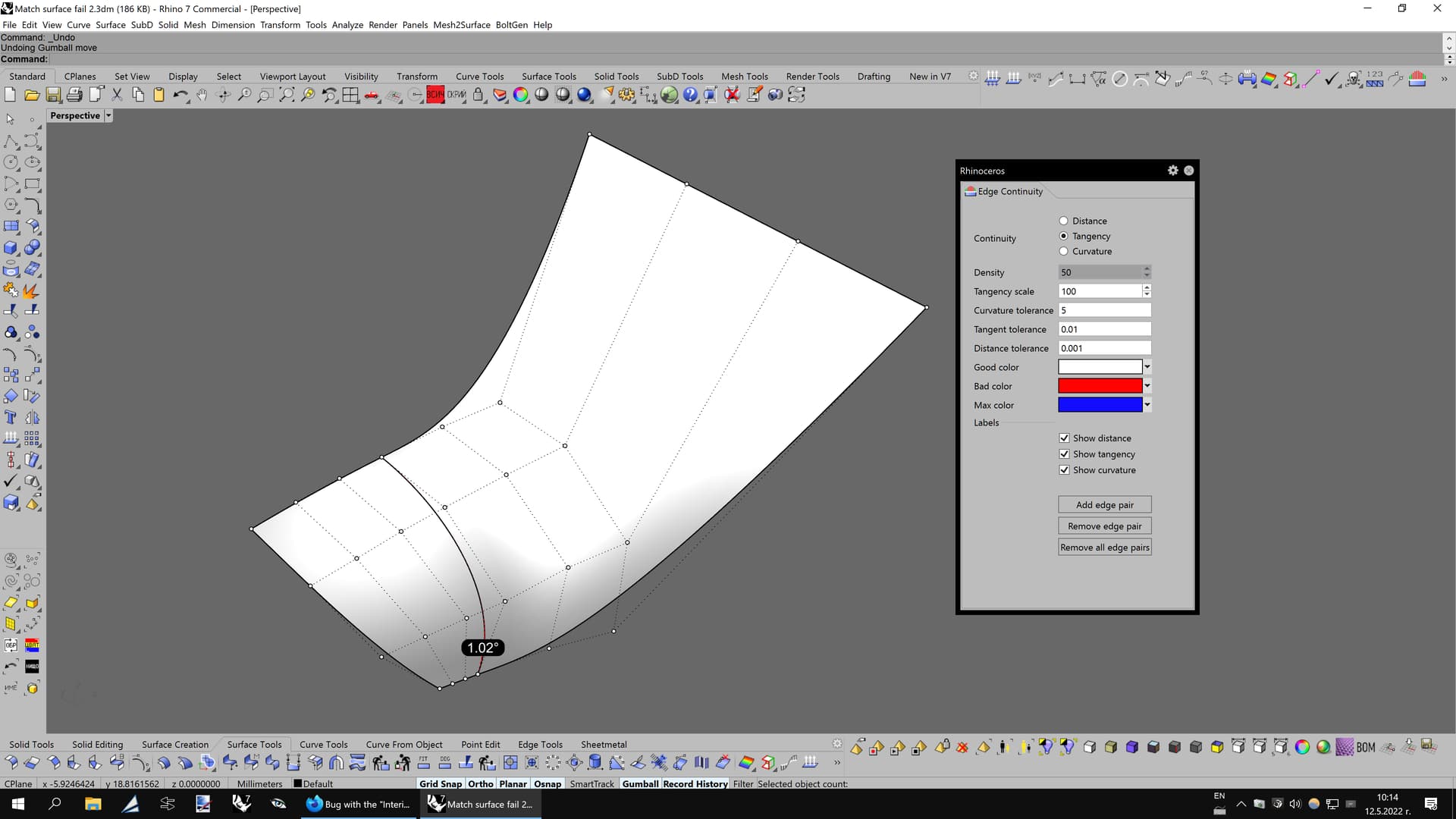
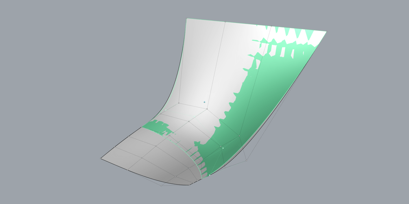
A pretty simple case where “Match surface” fails to achieve acceptable results despite that both surfaces have the same degree and control point count. Is that a bug or I do something wrong? The control polygons across the adjacent surfaces also don’t match quite well when you turn on the control points.
I think it is a combination of how the geometry of NURBS surfaces works and how MatchSrf is designed to work. Exact tangential continuity along the entire length of the edges requires moving control points towards or away from the edge. MatchSrf appears to only move control points more or less normal to the surface and does not change the distance from the edge. My guess is this behavior by MatchSrf is intentional. By only moving control points normal to the surface exact matching may be only possible at a discrete set of locations. That is why MatchSrf has the “Refine match” option which adds knots and control points as needed to achieve the match within the requested tolerance.
I’ve been looking into the math of tangency and curvature matching of surfaces and it is much more complicated than the equivalent matching of curves.
I don’t know why is this happening in Rhino, since Alias could do it perfectly. NURBS should be NURBS in every program. Also, I was able to achieve 0,5 degrees manually by moving the 2nd row of control points along their normal direction with the “MoveUVN” tool. It’s amazing that the automatic “Match surface” tool can’t achieve less than 1 degree of tangency.
Presumable Alias moves control points in a direction tangential to the surface as well as normal to the surface. See the examples of exact matches I posted above and compare them to what MatchSrf provides.
It appears that in your example MatchSrf provides an exact match at the side edges. My guess is that is by design. What was the match at the side edges when you manually moved control points?

")

 The good thing is that “McNeel” made this forum and actively listens to people like us, who are doing full-time modeling work for living, and fortunately they really implement some of our requested features in future releases of Rhino. I really want Rhino to become better and this is why sometimes I try to offer some new suggestions for improvements. These are usually a result of facing modeling challenges during work whose solution does not exist yet in the Rhino toolset.


")