I am constantly coming up against examples of erratic operation of the Solid Union and Solid Difference components. I think like a woodworker - making simple objects; gluing them together; cutting holes in them; gluing on more… But I often encounter cases where they simply don’t combine correctly, or, when I come to make a mesh, it has bits missing, and naked edges.
Here is an example. If I keep the geometry where it is, I get naked edges in the mesh. If I move the whole of the geometry one millimetre to the side, everything works!
[Warning - takes about a minute on my machine to do the solid union] Note that my original pentagonal curves are not all in the same z-plane.
I’m not so much after a fix for this current issue, as guidance from experts as to whether there is an idiot-proof way to combine arbitrary solids and get a good mesh at the end of it? I have spent days twiddling with Options Units and Options Mesh Smooth and Slower or Custom, and with different ways of doing the meshing (Weaverbird Join Meshes and Weld, etc), and most of these work often but fail mysteriously now and then. Clearly I have precision problems relating to my objects having common faces or some such.
Is there anything that ‘just works’? I see TriRemesh coming up, which appears to wrap up anything in a new watertight mesh. Is that going to be the solution to these problems?
Sure, that’s a common problem.
One of the rules of solid boolean operations in rhino is: “don’t use solids that have aligned/tangent faces”. Your case have almost all surfaces twice, in-place. That’s not going to help.
In your situation i would try to work with curves to create meshes, avoiding completely solids.
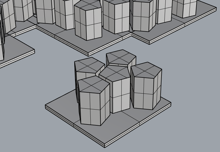
Each element/side of the pentagons seems to be an “extruded polyline”, so a simple quad mesh with sharp (unwelded) edges will be easy and fast to compute and display.
That’s perfect!
So, ask yourself: “is this shape possible in real life?”
Edit: looking only from top might seems “easy”, but the same part on the bottom links differently:
If you really need this exact shape, it’s a problem both for simulation AND real life manufacturing.
Why are you doing a solid union of the whole? How are you going to use it?
Why does it need to be watertight?
Asking for better understanding the situation and bypass the problem (if possible).
Thanks for coming back on this! My aim is to end up with a single mesh, which I can export as an STL file for 3-D printing. I also have a large CNC router, so a secondary aim is to have a surface that can be carved from above. My current project is something I described in Penrose Tiling. The example here is a very small piece of this.
The meshes with artifacts seem to to be generally accepted by Shapeways, which has some pretty good tolerance to being fed strange meshes. They have successfully printed the linked Penrose Tiling, although not with the same version I uploaded there, which is quite definitely nowhere near being a closed mesh solution.
Philosophically, you ask “is this shape possible in real life?” I see no reason why a union of a set of smaller objects each of which is valid in its own right should not be also be valid. How could it be otherwise? The fact that they may be inter-penetrating or share common surfaces is a problem for the Solid Union to sort out, not a problem in the development methodology! Although I can see that it does not actually work reliably! I see it as a very poor feature if shifting the whole geometry to a different location should cause the meshing to suddenly start working or not!
You have made me realize that a rather simple change to my script to avoid using Offset Curve with an equal offset on Both Sides, but instead to have different offsets on the inside and the outside, would possibly arrange that two objects based around the same line would not share faces exactly. I will try that here.
What I was really hoping for was the idea that there was a plug-compatible replacement for Solid Union and perhaps for Mesh Brep and Weld Mesh that would take an arbitrary set of solid breps and make a mesh that totally encloses them, wrapping their external surfaces. This would be watertight and and well defined. And certainly possible in real life! Maybe I expect too much!
You talking about thinking like a woodworker made me assume it was an actual big structure or such…
This solid have “steps” also on the bottom side…
If you don’t care about bottom side, that would be useful to know, that would help the calculation and speed up times.
Sadly i’m not working with meshes, then. Slow stuff.
Anyway, a good combination of “Merge Faces” and the fact that we can make the holes later, you can have this:
Yes, I do intend to be carving it. The 3-D print version is fine with the naked edges, or at least Shapeways is cleverer than I am.
In the real object I am making, I have various patterns which I am attempting to combine, one at each corner of the pentagon, merging into each other. This is just one of the six patterns. I have a clipping plane pentagon at the Z origin, extending down, and all the six different patterns decend into it. For that reason I am not bothered about the jagged bottom surfaces - they are all inside the base.
I will play with your Merge Faces approach. Thanks very much for this idea.
I took the reverse approach, and built on your observation that one should not have aligned or tangent faces. I made my inside curve offset different from the outside curve offset, so that none of the vertical faces are co-planar. I then did the opposite of your Merge Faces, which was to jog the pentagons up or down, differently for each pentagon, to force the top (an bottom) faces to NOT be co-planar either. And… it still does not work!
I do see a pattern though - all the naked edges are for lines that have an end on the x=0 plane. Moving the entire geometry by 1 mm means that there are no longer any lines that end on the x=0 plane. I think that this is basically just a bug in the Solid Union or Mesh Brep that cannot handle edges with x=0.
Unfortunately, this is symptomatic of a lot of the problems I seem to get with the joining and meshing processes, so my original question still stands - is there a plugin or recommended workflow that avoids the possibility of failure? I will play with Merging Faces, but it is not what I had in mind!
From my experience, the better you avoid co-planar faces, the more reliable the solution.
In my definition I’m joining pentagons extrusions (without holes) that compenetrate each-other.
Then doing holes for last, that part have no co-planar faces at all.
I would follow that idea…
You are stuck in a situation where you want and need solid booleans operations of many
About plugins, I can’t tell. I use few of them and reluctantly.