Hi Rhino/Grasshopper community.
I’m working on a support structure that needs to be offset / thickened, depending on what’s found in testing it might need to be thinned or thickened in different areas. I’m wandering if its possible to create a custom offset/mesh thicken in which I can control a few control points around the original mesh’s outside edge? (as in the black line represents the fixed edge, and controlling the orange dimension)
I have literally no idea how to go about this and any ideas/solutions are welcome.
Apologies for the crude sketch or description happy to clarify. If its not possible no worries, Il just have to get used to manual surfacing.

Not sure if you are talking about a 3d shape or a 2d flat one…
Assuming 3d.
Offsetting a mesh is moving vertex by (local normal) * amount.
Sharp corners will mess up (i’ve used a fully filletted shape in the example ![]() )
)
Overall surely not a flawless method.
So here is a rough proof of concept:

variable mesh offset.gh (43.6 KB)
This is a pseudo-trivial solution with attractor method.
In specific, i’ve selected faces of a brep to make 2 different attractors.
Each attractor have its own offset amount value and decaying distance. (decaying is linear)
There is a global offset amount which is altered whenever a vertex is near enough an attractor.
In case of it being in range of multiple attractor, a weighted average is computed. (i think…)
Instead of face selecting, you can manually place surfaces near the areas you want to have a different offset.
Hope it helps!
1 Like
I imagine if you are better than me at this stuff you could run a FEA on it, use populate3d to fill it with points, and from there make the mesh for the FEA, then you could input the local stress at each element and multiply to scale the voronois volumes from each populate3d point, then shrink wrap the results with that new trimesher or whatever it’s called, to make the new more optimized shape.
Hi Riccardo that’s amazing, almost exactly what I was after thanks so much. And yeah its a complex 3D mesh, sorry thought I had attached my File.
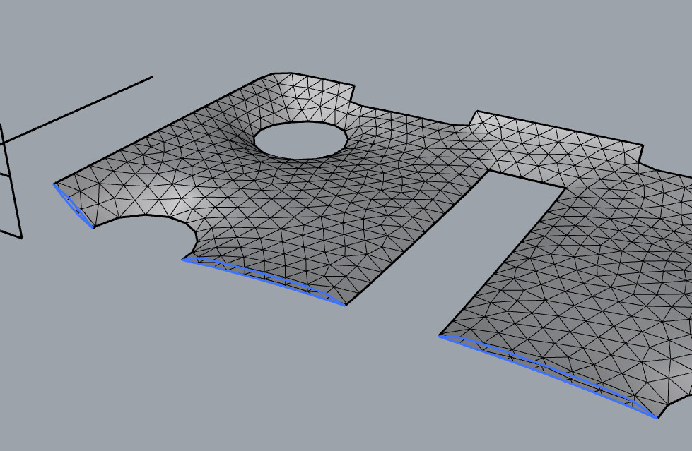
One of the problems I’m Having now is due to the complexity of the mesh all the faces are successfully offset however its partially disconnected as there are gaps between the faces. I’m currently thinking of trying to reconstruct the mesh with points, or a shrink-wrap tool though any suggestions would be great. However the end outcome is I want to be able to loft between the bottom and top surface which limits a few options. Anyway thanks again for your help and any suggestions on how to fix the new problem would be much appreciated.
Trimesh1.stl (40.0 KB)

Hi Jayandrewscadd thanks, that’s a good suggestion and will look into it, unfortunately dont have any stresses at the moment so am going off eye at least for now, though in future this method might be better. Also unfortunately Tri-Remesh doesn’t seem to work with the offset mesh I create properly as the mesh has already been produced from that tool. Thanks again 
There shouldn’t be any problem remeshing the offset - it’s just a mesh like any other.
It looks like your offset isn’t working though - like you’re treating each individual triangle as a separate mesh. You need to move the vertices of a single mesh then rebuild using the face list of the original.
1 Like
Hi Daniel your completely correct, my mistake I was using face boundary and boundary surface to solve another problem and reused a brep from there which caused all the triangles to be viewed as separate mesh After I solved the dumb mistake it all but fixed itself and I have a solid mesh with no offset gaps. Apologies
No problem.
Here’s a simple way of making a variable mesh offset - in this case with thickness as a function of distance from the boundary

variable_offset.gh (51.3 KB)
Also - I noticed that your shape from the other thread has some tiny spikes on the edges of the Brep:
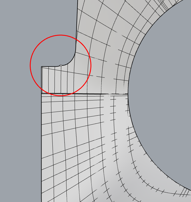
When using TriRemesh on the Brep, by default it assumes sharp features like this are intentional and should be preserved, and if these sharp features are closer together than your target edge length, this will cause lower triangle quality there.
If they are accidental though, one easy way to avoid it here is to pass the Brep through a Mesh parameter first - then it only treats edges with an angle above a threshold as features.
TriRemesh_mesh.gh (1.5 MB)

2 Likes
Hi Daniel Piker,
Damn that’s an incredible solution and insanely compact to what I had at first so thank you. Unfortunately the edges are what I’m trying to increase the thickness of, apologies for my bad explanation and another crude diagram.
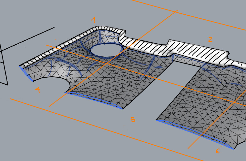
I could probably edit your solution above to work in an opposing manner, however I’m looking for more control over the edges + global offset. With the first solution I’m trying to add more attractors / surface attractors so I can split control of the edges to have a variety of thicknesses.
(possibly into a minimum of 6, sorta all corners + the middle of the long edge section) Proving a tad difficult but that’s my end goal, thanks for your help though and any other better solutions always welcome.
O and your quite right the surfaced shape has a few problems with it which i tried fixing manually. I received it after taking over this project but I hadn’t noticed that edge spike so thanks, and that’s a much easier solution to fix mesh errors in future so thank you will keep it in mind when I received other surfaces to repeat this method.