UV mapping Bug?

I’m having problems UV mapping meshes in Rhino.

Steps to recreate problem:

  1. Create mesh sphere with command _MeshSphere using default settings (10 Vertical Faces, 10 Around Faces).

  2. Run _Unwrap command on sphere with seams as shown:

  3. Check UV layout with _UVEditor command:


    All looks as expected.

  4. Export using these settings:
    export_1
    export_2
    export_3
    export_4

  5. Re-Import using these settings:
    import

  6. Check UV layout with _UVEditor command:


    UV layout is messed up now. Importing this mesh into ZBrush, Blender, and 3DCoat also shows this messed up UV layout.

I get these same results with:
Mac Version 6 (6.27.20163.15072, 2020-06-11)
Mac Version 7 WIP (7.0.20168.12016, 2020-06-16)
Win Version 6 SR27 (6.27.20163.15081, 6/11/2020)

Same results exporting / re-importing in OBJ & FBX formats.

-Kevin

Hi @kev.r, that happens because OBJ export doesn’t include full information about the texture mapping applied by Unwrap command. Mapping is exported as UV coordinates on mesh vertices. Therefore it’s not possible to introduce texture discontinuity on welded areas of a mesh in OBJ export. One way around this issue is to use _Unweld on the texture seams before exporting.

Correction to above response. The correct command to unweld edges is _UnweldEdge.

This looks like the same issue as RH-32866

So you have to _Unwrap then mark the same seams again and use _UnweldEdge?

Seems to work, but an unnecessary duplication of work (especially if you’re unwrapping a complex model).

Guess I’ll have to unwrap my models in another software package until this is fixed (original bug reported 4 years ago).

-Kevin

You could also unweld all edges using _Unweld with Angle tolerance set to 0 and Modify Normals unchecked.
I’m considering a new command to automatically unweld texture seams. Or making that part of _Unwrap command as suggested in RH-55189.

1 Like

This makes each face an isolated UV island - seems undesirable to me.

Adding options for _UnweldEdge and Modifiy Normals to the _Unwrap command seems the most straightforward solution to me.

Thanks for looking into this.

-Kevin

Looking into this again.

If it’s not possible, how is it done in Blender, ZBrush, and 3DCoat?

1 Like

Thanks @kev.r, that is a very good point. I suppose they simply unweld edges on texture discontinuities. @tim, do you think Rhino could do that?

I don’t think so.

Here is a model of a simple sphere I created, unwrapped, and textured in Blender. It has 8 separate UV islands and all mesh edges are welded.

Exported from Blender as obj and imported to Rhino. It looks correct when I run _UVEditor:

Also looks correct in rendered view:

12x12_uvsphere.3dm (3.2 MB)

All looks good when I run _Check on this mesh - valid closed mesh with no naked edges.

I can produce the same results UV unwrapping in ZBrush and 3DCoat as well.

-Kevin

@Jussi_Aaltonen

Something I don’t understand.

After you run _UnweldEdge, shouldn’t the edges you unwelded be detected as “naked edges”? You can see them if you have “Mesh Edge Settings” (under “Display Modes”->“Objects”) set to be thicker and/or a different color.

The file I posted above from Blender looks like all the edges are unwelded (didn’t notice it before I changed the “Mesh Edge Settings”). The edges all appear to be connected when I look at it in Blender - strange.

I’ll look at this further tomorrow - out of time for now.

–Edit-- next day - further investigation:

There are definitely differences in how meshes are handled in Rhino and Blender.

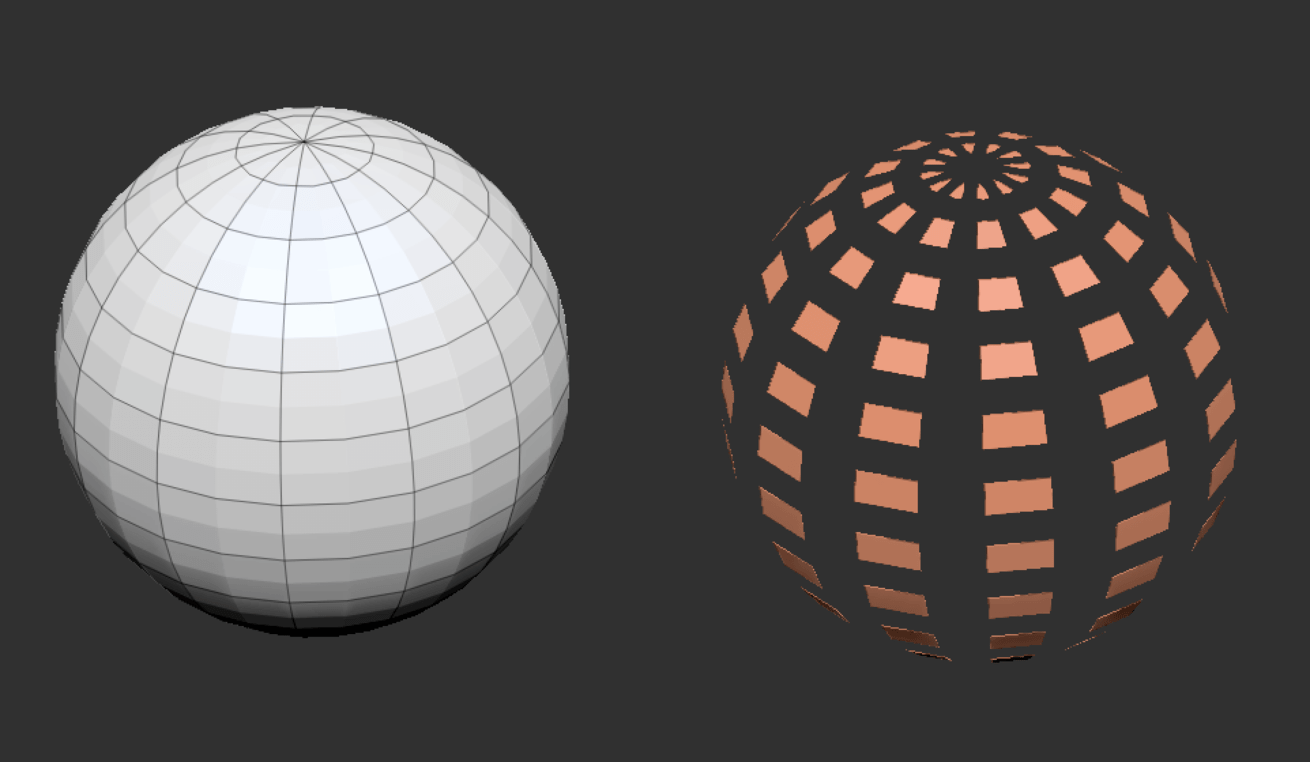
In Rhino V6 I created a mesh sphere, copied it and ran _Unweld with Angle Tolerance = 0 and Modify Normals unchecked.

The unwelded mesh looks different because of display mode settings:

I sub-object selected a face on each mesh and moved it - you can see that the faces are all still connected:

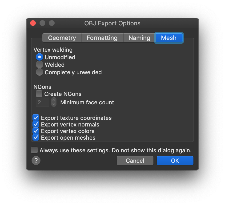
I exported this file to obj - I know there is a setting for Vertex Welding on export, I have it set to “Unmodified”:

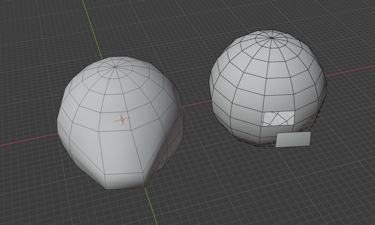
When I open the file in Blender and examine the unwelded mesh all the edges show as Non Manifold (Boundaries).

If I grab and move a face, you can see the faces on the unwelded mesh are not connected:

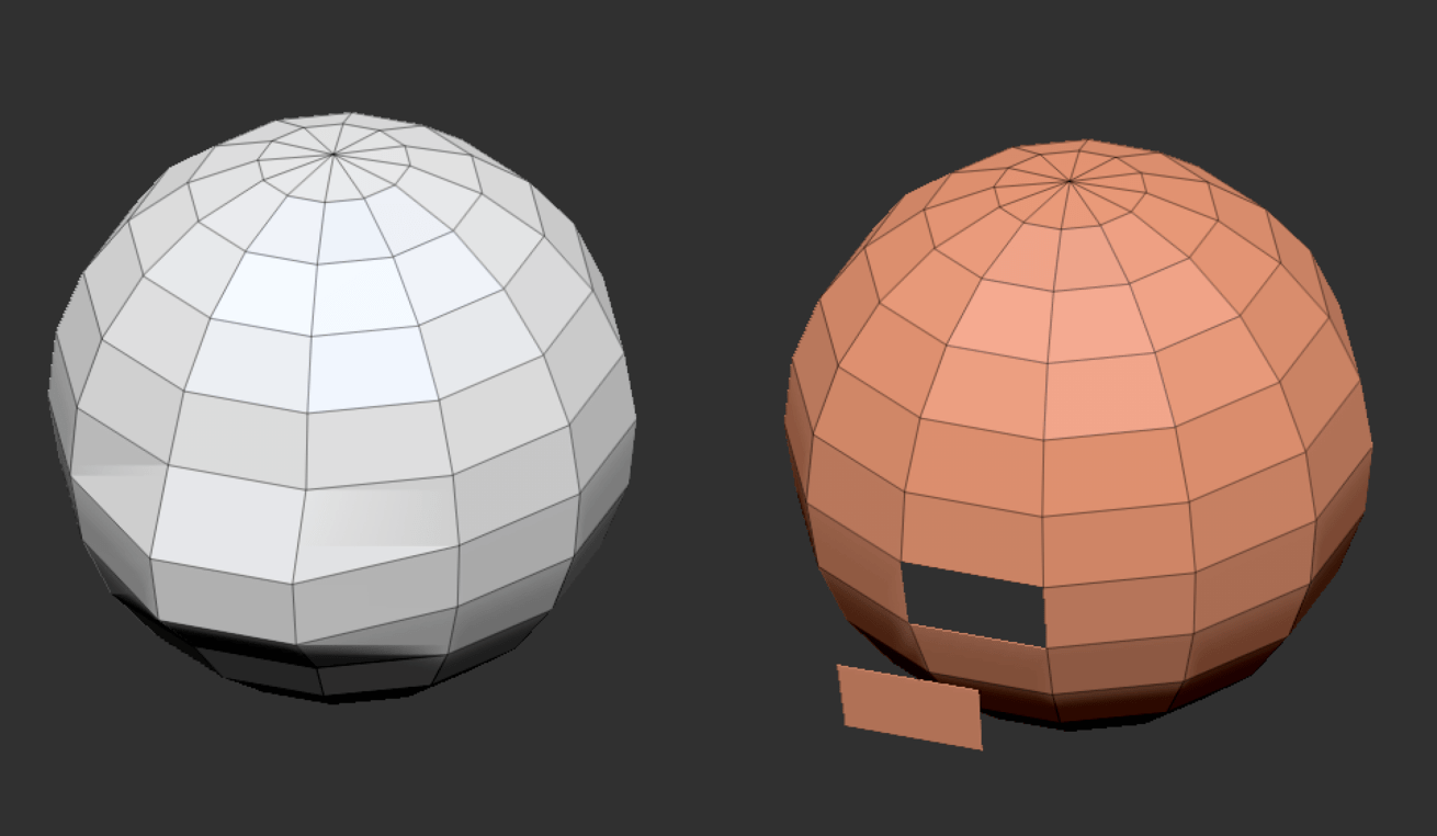
You can also see the effect if you apply a Subdivision Surface modifier - all the disconnected edges shrink away from each other:

The same effect can be seen in ZBrush if you move a face:

Or if you divide the mesh:

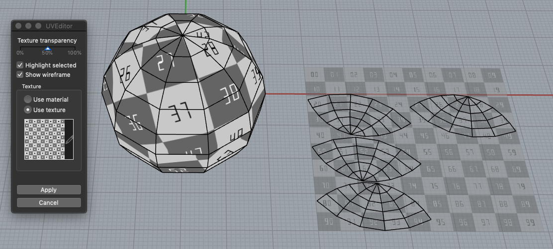
Back to the original topic of this post: If you have to unweld edges in Rhino to be able to have disconnected UV islands, or as you called it “introduce texture discontinuity on welded areas of a mesh in OBJ export” - the disconnected edges cause undesired side effects in Blender and ZBrush. In both of these programs you can UV map a mesh with disconnected UV islands without disconnecting edges.

Apologies for being so long winded, trying to explain clearly.

-Kevin

Hi @kev.r

It appears the meaning of the word welded differs a bit between different software and file formats.

I took a look at the Wavefront OBJ file format. It allows each mesh face corner to reference vertex point, vertex texture coordinate and vertex normal separately. And it appears as if welding in Blender means that the corresponding vertex point indices match on the faces connected to the edge. Texture coordinate and normal indices don’t need to match.

In Rhino welded edge is defined the same way but there is a difference because of the way meshes are defined in Rhino. In Rhino each face corner has a single index that indexes all of the vertex point, vertex texture coordinate and vertex normal arrays. That implies that in Rhino edge being welded means that that edge can not have any kind of discontinuity - neither in normal nor in texture coordinates.

I sketched a Rhino 7 model to try to illustrate this: RhinoMeshIntro.3dm (574.0 KB)

According to my tests the Vertex welding setting in OBJ Export Options has to be set to Welded so that discontinuities in texture coordinates and vertex normals are preserved but the vertices stay welded in Blender.

1 Like