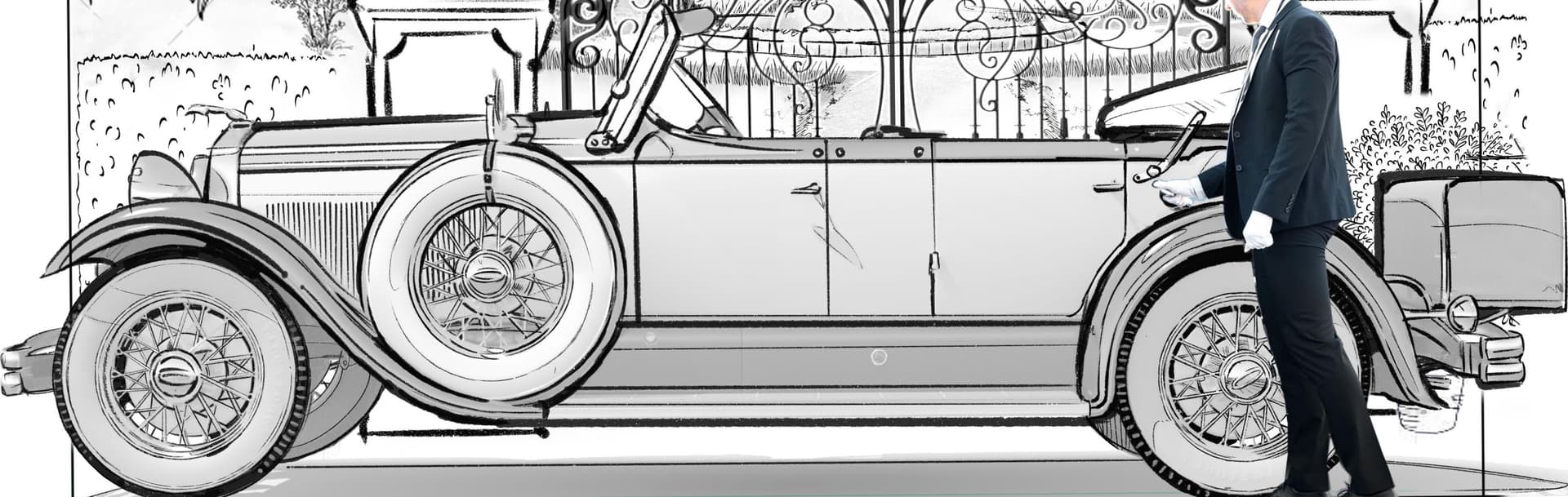
When the UV Editor is open (Bottom of first Image), the resulting mapping visible in that image (on the surface above) it doesn’t match the polysurface placement set and visible in the UVEditor. (The headlight and windshield show it worst).
Misalignment with UV Editor open:

Hi Djhg
Can you post the file? Thanks
Thanks Japhy. Just uploaded it. The problem is visible in the back view viewport.
I’ve moved the polysurface representation to align the mirror and windshield but this gif shows what’s happened with the wheels, and how the display misrepresents it. The wheel area seems to have displaced more than I have moved the entire surface representation to align the windshield and mirror

.
Thanks, we’ll need the texture image as well. Thanks

This is a bit out of my arena and i’m trying to understanding the process & underlying geometry to see where your issue is.

Here i did a mesh outline of the one you are showing, created a PlanarSrf and applied the texture and the alignments look good.
MisalignmentInUVEditor-Car.3dm (5.2 MB)
Thanks Japhy, but it’s not aligned. There’s almost no black showing of the front tire.
The task here is to design a panel with edges that will align with those of a printed graphic to be applied to it.
I created the panel surfsce by tracing its boundaries from an iteration of the image inserted. But when I apply the image to that same panel object to illustrate the result, I have not been able to align it.
Something’s off somewhere.
At one point I seemed to need to edit the nodes of the polysurface representation in the uv editor, which should have warped the relationship between surface and image from how it was when I traced the surface boundary to match it.
At another point it appeared that the representation of the polysurface showed a version of the panel polysurface which was not up to date with all edits done directly to the polysurface, and I had to reproduce them in the uv editor. For example the polysurface and image has a flat spot where the tires meet the ground, but the original polysurface prior to editing to match this image was continuously curved at the bottom and I straightened it to match the image. Then when I went to apply the image and opened the uv editor, the bottom of one of the tires in the representation was not flat.
Either I am making an error somewhere in this process, or uv mapping doesn’t operate at a resolution accurate enough for this task.
Hi @djhg,
I think the issue was that your surface with the reference image applied in the material that you traced was slightly wider than the aspect ratio of the image itself.
The Untrim command can be used on the original surface in the file to show the difference. Use the Picture command to bring in the texture on a surface without losing the aspect ratio and to compare to the untrim result.
You would need to retrace the border using the Picture surface instead. I’d suggest using the Curve command too instead of Polyline. End each curve and start a new one anywhere you need a sharp corner and then Join the curves together after and use the closed loops with Trim. Note that the Picture command also has a special material which doesn’t let shadows fall on it and shows up in all display modes. You can apply your other material to that surface after the trim if needed.

Thanks Brian.
I decided to redo the outline on the polysurface for fear of having made an aspect ratio error somewhere along the way.
The perils of having had “near” snapping on when unnecessary. Oops.
1 Like