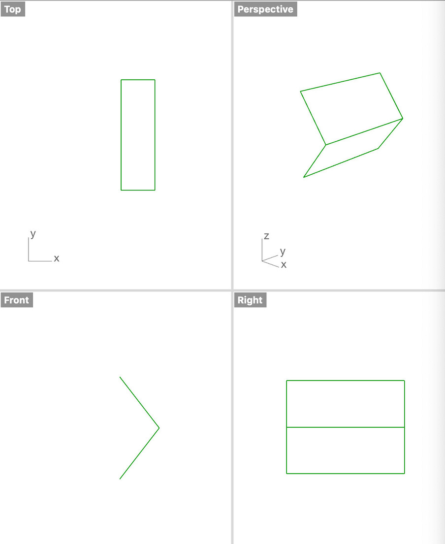
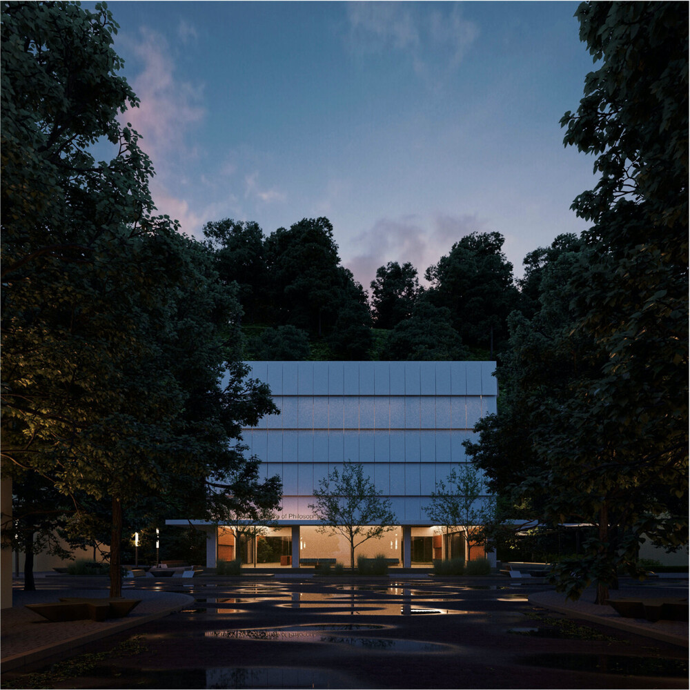
I’m trying to model the movement of an upfolding textile shading device, which should work like this (the bottom and top points should move in a vertical line):
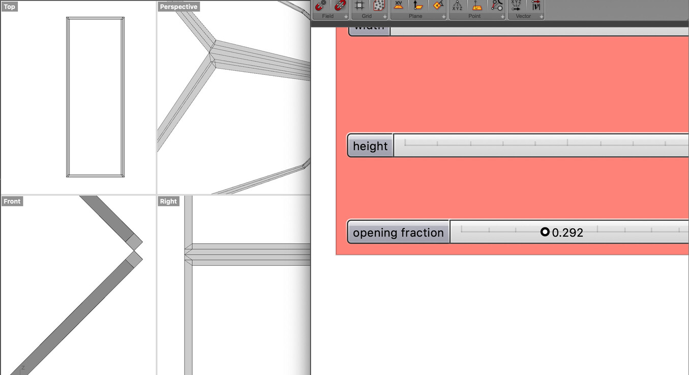
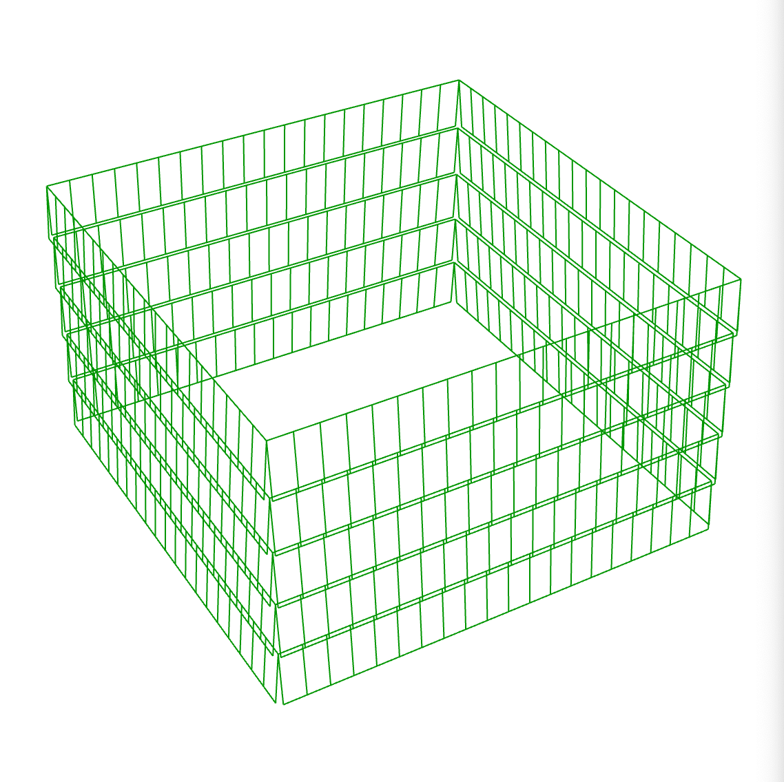
I created a Grasshopper definition that I would like to animate with an “opening fraction” slider in the end. However, I’m not nearly done yet… I fail to solve creating the frame sweeps in the proper direction, until an opening fraction of 0.292 it works as expected:
In general I have issues using Sweep1 with Grasshopper, I don’t reall understand why this is happening. If you examine the wireframe only, it moves as expected, I suspect I have problems with my Orient geometry and Sweep1 components at the end of my definition.
Any ideas how to do a proper sweep that wont flicker all around the rails? Or should I use some other command?
I’m a little pressed for time this morning so haven’t looked at your code yet, but you might find this old thread useful (though it drifts into thicken issues):
Thanks, @Joseph_Oster, I took a look at the thread and the script,it’s not exactly my problem that is being discussed there. I can do a solid plate, but I need to model a textile device, so I have to be able to change the profile later on.
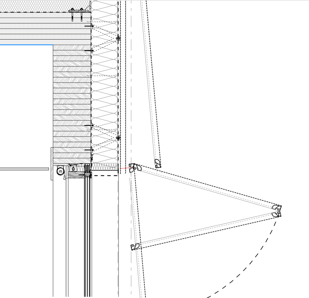
This is a work in progress section of my building to better understand the situation:
For this reason, @HS_Kim, your suggestion is not a solution now, unfortunately, as I won’t be able to alter the rectangular cross section, if I understand your file properly.
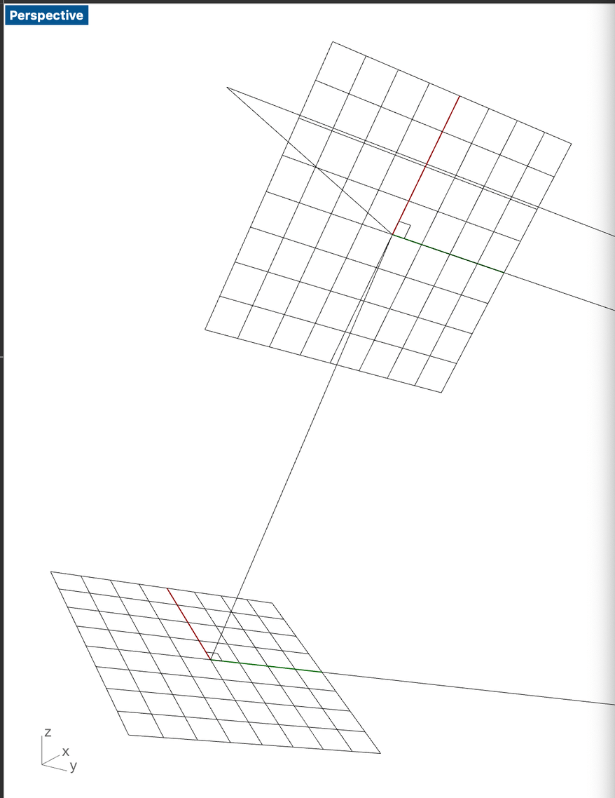
I think I found the problematic part in my definition: when I create the planes with a normal and an origin, it is free to rotate around that Z axis.
Is there a way to define the X direction for instance? That would be the bottom edge for each panel.
Notice the flip of the X and Y axis… This is how I define the “oriented plane”:
top normal is the left “vertical” edge of each panel, the Brep Edges is the frame of the panel - the start point should be the bottom left for each.
As long as you are using rectangular section profiles, my suggestion should work by adjusting offset and extrusion distance. But if you use section of custom shape, then you are right.
Yes, I meant custom profiles, sorry if I wasn’t clear.
This is my next obstacle actually: with a rectangular profile my script works now.
If I switch to a custom frame however (coming from the manufacturer as a DXF), Sweep1 dies even for the outline (in the Python component rs.AddSweep1 works), creating the full frame geometry is not working with either one.
Do you have anything in mind?
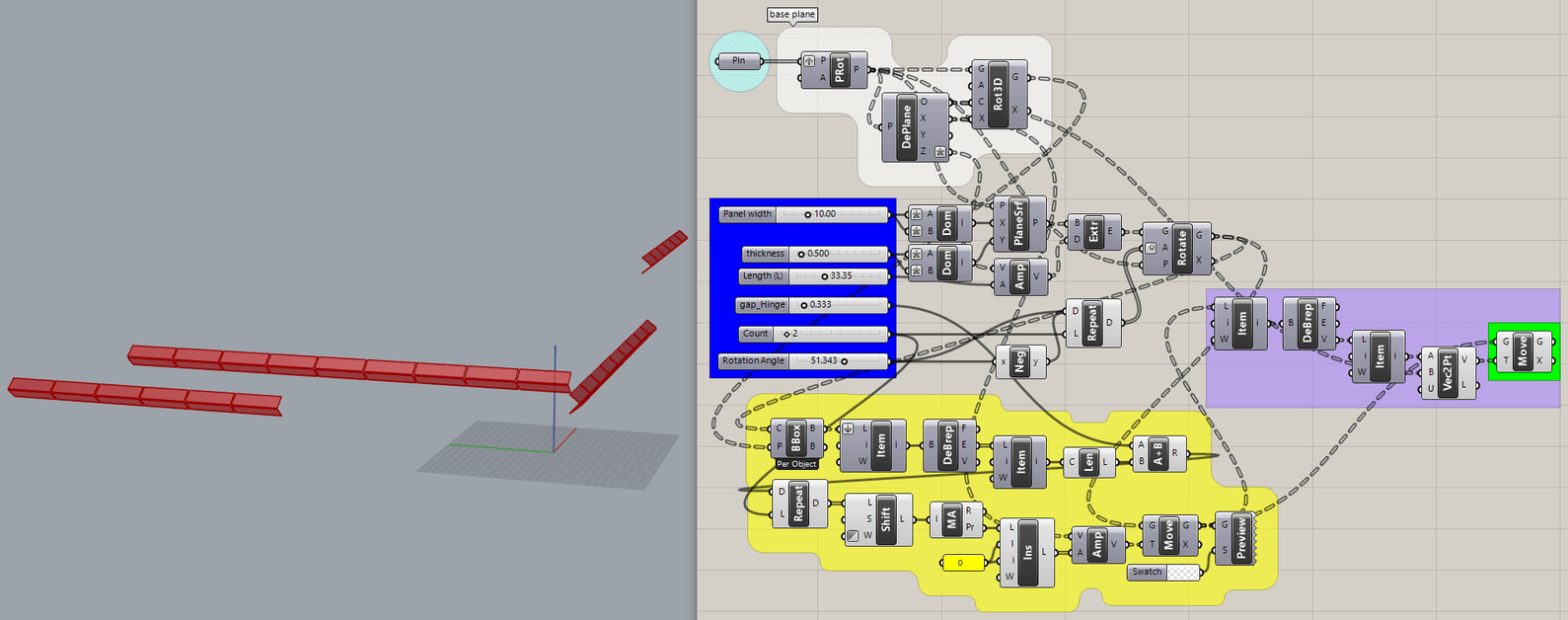
This is my updated script, the frame curves are internalised in the red group on the right.
The only thing I got from all your pictures is that your “Upfolding shading device” has only two sections and is fixed at the top. The old code worked only in the WorldXY plane so I fixed that and adapted it (hastily) to handle multiple sections.
The ‘gap’ slider is intended to allow for a hinge but that value can be reduced to zero.
The horizontal gap between sections is hard-coded into the Series ‘N’ input in the cyan group (a fixed value added to ‘Length’).
I’m late, gotta go.
P.S. I see that it fails when there are more than two panels. No time now to fix it.
And to examine all the other models posted in this thread. It seems to me that some abstractions are needed to take this further, such as:
Using a panel/frame that is constructed separately, with any arbitrary frame cross-section and size, as long as it amounts to a rectangular box. That single panel would be oriented and used as often as needed to make “upfolding” pairs.
Location and orientation of each pair (or vertical set if more than two were used) would be defined by a list of planes.
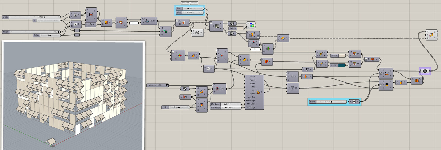
I tackled the second part first by isolating the code that uses planes from the code that creates the planes in specific locations (cyan group). So far, it works well when all the planes are either XZ or YZ but fails when mixing the two…
The problem was only in the cyan group, creating the planes. This model has an internalized list of 30 planes (one per folding pair) facing two directions at four different locations, How they are created can be determined separately, perhaps from properties of the building such as planar surfaces that serve as placeholders for each pair.
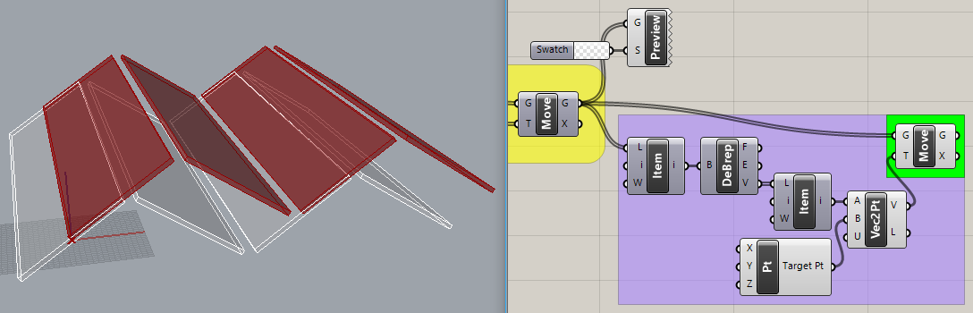
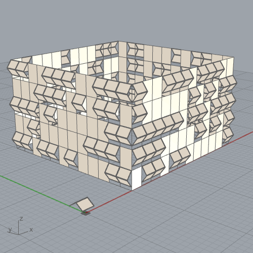
Getting there. The orange group is a building with Random Reduce applied to SubSrf(Isotrim) sections to represent locations (planes) for the folding devices (shown in white).
The ‘Custom Frame’ from @HS_Kim’s code is internalized and oriented to each of these planes (shown in yellow) but not yet used by the folding mechanism.
Interesting approaches, thank you! I will try to incorporate them into my model later today.
@Joseph_Oster your definition is really cool to think about tolerances (hinges, operating distances between neighbouring frames to fasten screws, etc.), which I haven’t yet accounted in my solution (it folds to zero at the starting position):
@HS_Kim I’m on my laptop now, and your latest file requires Lunchbox (I’m on a Mac when mobile and it is Windows-only if I recall), so I’m not able to test right now. When I get to my desktop I will, but it looks really promising on your GIF.
Thinking loud here about further issues...
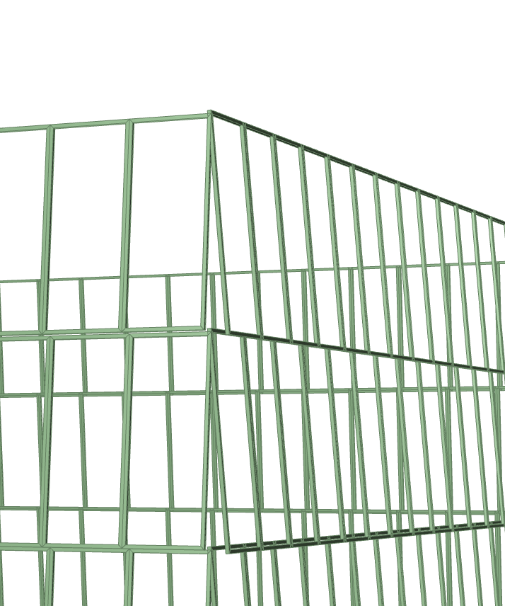
What I have issues now is the sorting of my subdivided surfaces, when I built the concept model I haven’t thought about actual structural detailing later on, so I have these annoying misalignments around the edges:
Maybe I’m better off now baking each side as simple surfaces, rebuilding the boundaries in a proper way, and applying the framing logic (either fixed or folding), .gh starts to lag too much now.
I cannot complain, this what you get when your model is becoming a dumpster fire hacked together weeks before a deadline.
I really appreciate the help, this proves to be a life saver for me. I think I can merge the pieces into a final solution.
I don’t have Lunchbox installed but I can tell from the animated GIF that only one pair of panels is being folded and then it is copied (usingOrient) to all the target planes.
Out of curiosity, I changed the ‘U Count’ slider in my model (orange group) from 3 to 10 and noticed a significant delay (~35 seconds?) that turns out to be caused by Orient in the gray group, which is copying the unused ‘Custom Frame’ to all the target planes. Disabling Custom Frame removes that delay. Re-enabling it freezes the GH canvas for ~35 seconds.
Wow, that’s costly compared to the way I’m creating the folding panels in place.
By the way, I’ve never seen that dropdown arrow you used and almost missed what it reveals when you click it. I see it now in the post editor, the ‘Hide details’ feature?
This is an example of the 'Hide details' feature (CLICK ME)
Lorem ipsum dolor sit amet, consectetur adipiscing elit, sed do eiusmod tempor incididunt ut labore et dolore magna aliqua. Ut enim ad minim veniam, quis nostrud exercitation ullamco laboris nisi ut aliquip ex ea commodo consequat. Duis aute irure dolor in reprehenderit in voluptate velit esse cillum dolore eu fugiat nulla pariatur. Excepteur sint occaecat cupidatat non proident, sunt in culpa qui officia deserunt mollit anim id est laborum.
Seeing how slow Orient can be, I made the ‘Custom Frame’ optional. It is now used to get dimensions (‘Length’, ‘Width’ and ‘Thickness’ sliders removed) but as noted in the gray group:
Enable Orient to use ‘Custom Frame’ (SLOW!)
How slow? Enough to make interactive folding impractical, even when the number of “folding devices” is low. When ‘U Count’ (orange group) is changed from 3 to 10, the number of planes goes from 24 to 304 and takes more than 1.5 minutes with Orient enabled, so default is disabled.
I’m not sure how else to do custom profiling other than Orient, but I need(ed) the geometric complexity, I don’t want to draw the profiles in 2D on all my sections (I bake the results into Rhino then export it to ARCHICAD as a Rhino 5 model).
I didn’t think the “detailed” model would be this heavy, I’m thinking about only using the rectangular cross section for lightness… At a scale of 1:50 the profile itself is not really visible anyway, but it bugs me.
Sweeping manufacturer provided frames is a generic issue which surfaces whenever creating windows, curtain walls, or other metal framings.
The interior details of the ‘Custom Frame’ are complex and completely lost at building scale. A much simpler version could be created that more closely approximates the dimensions and cross-section.
P.S. Here is a simple ''Rectangle Frame" that is much faster than the ‘Custom Frame’, though still slow interactively with a large number of planes.
I intended to create close up renderings from a section of the facade.
It must have been the food coma after Christmas that I am recovering from now.
I recall seeing quite detailed structural models on this forum, but I couldn’t find them now, I’m wondering how they are managed.
I managed to open it. The operation is really fast, I like how you reused half of the folding panel to scatter it across the surface.
I wonder if this method is the trade-off for speed. I was thinking in panels from the beginning, maybe it would be better to create a set from all the different sized closed polylines and use blocks to populate the facade
Me neither. If I’m correct, there isn’t much native components to define and manage blocks in Grasshopper, right? So I need to use the likes of Human, Elefront, etc.?