I am trying to extrude the Voronoi lines so that I get the side surfaces. But this requires that I have a normal vector for each cell. This trick didn’t work because Voronoi cells are not planar. I ended up using scaling the center points for the vector. But unfortunately this completely skews the side surfaces in some areas. voronoi.gh (87.7 KB)
thank you so much @Quan_Li
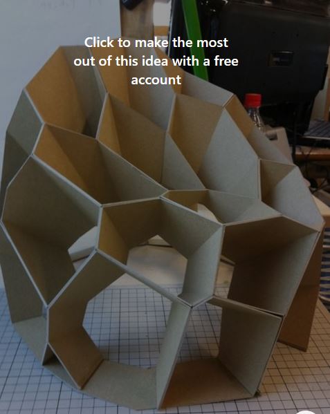
but i think two problems is seen in your model
first, the extruded cells thickness is not different. it is wished that an attraction point was existed to pull the thickness of cells differently
and second, the rows placed on the floor is not flat however i know its algorithm is complex
Create FLAT Vor Polylines. Exclude (or not) the Polylines in contact with the Rectangle frame (used to provide the Surface for the rnd Vor pts).
Morph “map” these to the target surface (that’s waay faster than Morphing Breps out of these Polylines). In fact you can Morph only the Poly pts (suitably sampled in a Tree). That’s way faster.
From each current Poly pt (from 2) get the Surf Normal and the previous/next pts and the Bisector Vector ( i.e. previous - current, next - current Vectors).
Use basic trigo to define the thickness using the Bisectors.
So … per Segment you have 4 points: current, next, next acc 4, current acc 4 and their positions from the equivalent Normal Vectors (from 2). So you can create a Solid (or better/faster a Mesh) on a per Polyline and Segment basis.
This allows to build self supporting/stand alone “rings” per Vor Polyline that is way easier to assemble - in real life - than creating Solids/Meshes per common (adjacent) Polyline/Polyline segment (that requires rather complex invisible joints).
In fact in real-life this requires torsion free beams/Items … but this is another animal (solvable via K2).
thank you @ajarindia
your first try all cells was in one direction that it wan not my solution
but the second solution is thing that i want but considering the real image in the first topic, the amount of extrusion for each edge is different ; how we can do this?
It’s very very easy … provited that you know how to code (but alas this is not your case). Since using native components is not my game I don’t know how to do it that way.
Anyway I could provide an indicative C# solution - MINUS the torsion free part that is strictly internal (but if memory serves well in the past Daniel posted something similar but I can’t recall the thread name).
BTW: since “exact” mapping of the 2d Vor Polylines has no meaning (at all) mapping just Poly points is the way to go.
BTW: I hate Voronoi for real-life things (in the broad AEC BIM market sector). One of the reasons is that you MAY arrive into Polylines with tiny segments (that obviously can’t yield a real-life piece/beam of something [done via wood/glass/metal/plastic/whatever]). One way to deal with that is to use a randomly distorted ortho Pt grid instead of “true” random points.