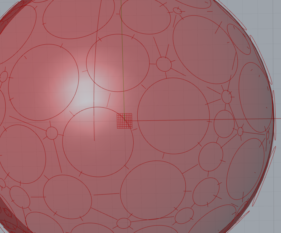
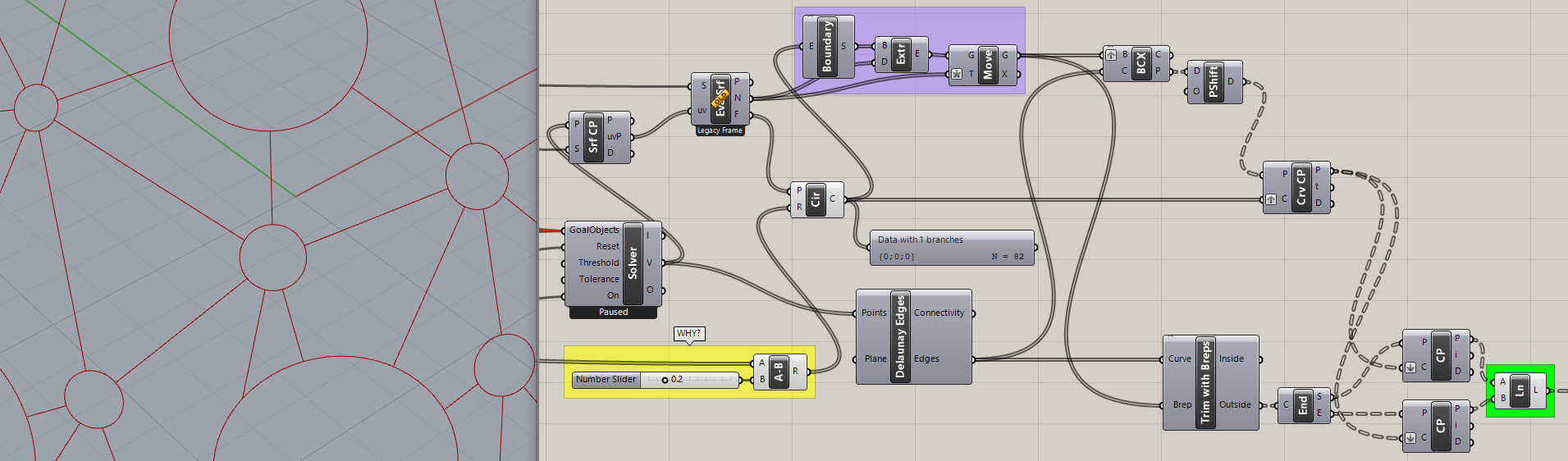
I’m trying to trim delaunay edges on a 3D surface similarly to a flat surface, it seems to not work very well. I tried doing it with a brep instead of a curve, but it still has some uneven edges. It doesnt necessarily need to be trimmed as this slows down the system a lot, but is it possible to get the intersection of the edges between the circles trimmed on a 3D surface?
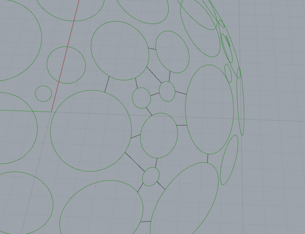
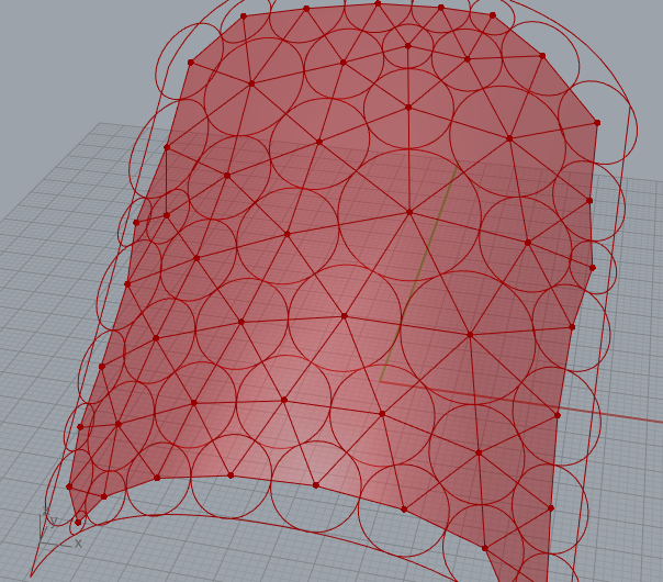
Third picture is kind of what I want to achieve, i did it manually in rhino, but was thinking there should be a way to do this with delaunays in grasshopper
When you triangulate points on the dome, the Delaunay edges are straight and do not lie on the surface.
Therefore if you take circles centred at the vertices and extrude them then trim the lines with these, the resulting line segments will not touch the circles.
Do you want to make straight lines between the circles or curves following the surface?
I would to make straight lines between the circle edges. so that the tangent line can be split with a mid point, so that the circles can be connected with each other. I tried to make new circles in the points that was left in the intersection which seems to work a bit better. But yeah, to connect the circles with one another is more important than the structure underneath.
it avoids the slow boolean cutting operations, and also since the connectivity is based on radii and proximity, it avoids the need for the Delaunay triangulation (which gets distorted at the sides because it only works in-plane)
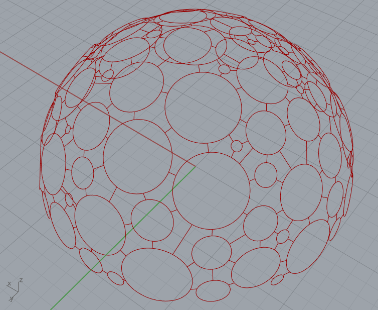
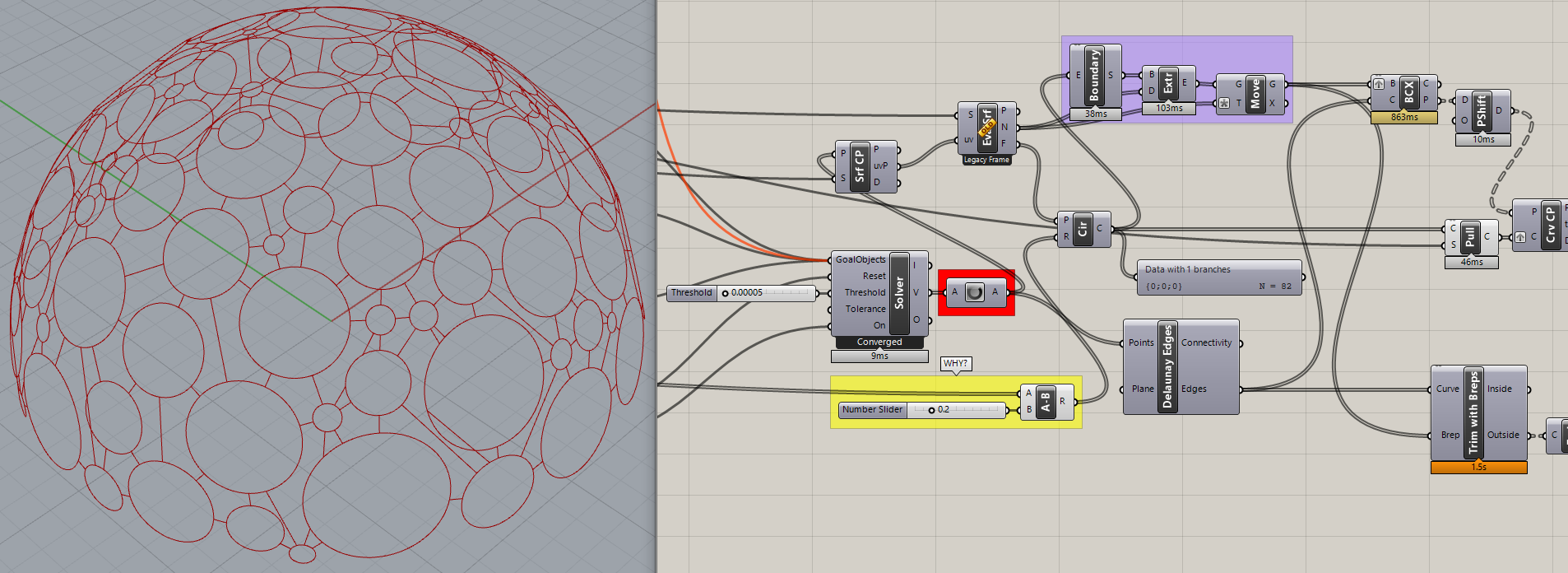
I noticed that very short lines were missing from the first version I posted so I fixed that using Pull to get the circles onto the surface of the sphere. Also set the yellow group slider to zero.
I noticed that @DanielPiker’s solution showed fewer connecting lines than mine. That can be adjusted by increasing the value of the last slider in his model that affects the SmallerCull at the end, but that seems a little arbitrary?
My solution was very slow so I tried adding a Data Dam but…
The Solver never converged, causing GH to run slowly (it doesn’t converge in Daniel’s solution either but the burden is much less).
So I added a ‘Tolerance’ value to force the Solver to converge and stop. Much better! Except the Solver progress isn’t visible anymore, but that’s cosmetic.
Thanks! Your solution works a bit better for for what I’m trying to achieve. Since its based on delauneys and the mid point works i can extrude it based on the normal of the surface, its a bit easier to work with. But I will see how it compares in terms of speed.
Well, it uses Delaunay Edges to find intersection points with the extruded circles but then reconstructs the visible line segments based on Crv CP to the “pulled” circles.
I noticed an extraneous line segment and realized that I didn’t extrude the circles far enough (purple group) to intersect those edges properly. So I added the cyan group and did a little testing to come up with an amplitude of “5” for the extrusions (plus and minus 2.5). That’s a little arbitrary too but could be derived, perhaps based on the circumference of the sphere.
I just wonder one thing about your definition.
When i’m trying to get the midpoints from the lines that are connecting i get these extra points that are not on the lines. Is it possible to cull these straggling points and only get the lines?
Oh ok, thanks for the feedback, i managed to get the results I wanted by rebuilding the curve, but maybe the tolerance will work as well. I needed those points to disappear because the points will be used to create circles on them, and there cant be any uneven points
Correction, it was setting a very smallSolver ‘Threshold’ input value (0.00005), not ‘Tolerance’, that caused the Solver to halt at a “Converged” state. I don’t know what the difference is between the two?
Threshold is the energy level at which the simulation stops iterating.
Tolerance is the geometric distance below which points in the initial input get combined into a single particle.
It does say this in the mouse-over text for the inputs. If someone has a better suggestion for short names that would be more intuitive I’m happy to consider them though.
Also, regarding the extra points, I see in my earlier definition I got the connections by finding points closer than the sum of their associated radii, but in a way that included the comparison of points with themselves (which are obviously always at zero distance). Adding also a ‘larger than’ check is one way to resolve this. You could also do it with a different approach to the data matching.
…also - what is the overall aim in this design?
Depending on the intended result, I think there could be easier ways of achieving this.
Packing random sized spheres using collisions, then connecting the spheres which touch, will generally not give a triangulation. You can triangulate the points, but then some of the connections will be spanning between spheres which do not touch in the simulation, so will be longer than others.
If a triangulation is the aim, and the circles need to be of varying size (but the exact radii do not need to be specified in advance), then a better way is to work from the triangulation, keeping the topology fixed, and adjusting only the distances. The TangentIncircles goal creates meshes where a sphere centred at each point can be drawn so that it touches all of its neighbours in the triangulation: tangentcircles_mesh.gh (13.7 KB)
First off, many thanks to both of you for your amazing support.
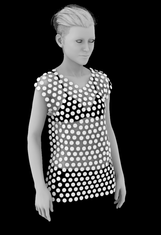
Yes, the aim is to use the random sized circle packing definition to create discs connected with rings.
The end goal is to apply it to an imported mesh.
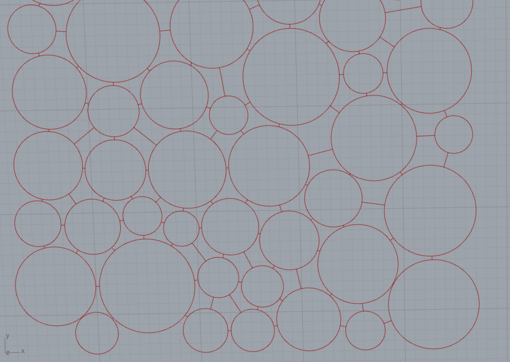
So the main goal is that they are all interconnected, and that a set of standard sized rings can be used to connect the discs, therefor it is important that the space between the connections can be put in half.
Here is a 2D representation of what needs to be done, but i need to make this in 3D. and apply to an imported 3D mesh. This was quite easy on a flat surface but when on a 3D surface it is more complicated.