Hello lads,
I’m trying to make a simple model of a membrane, but I can’t figure out why Karamba is giving me this error.
The error warning is:1. The structural system buckles under the given loads in 216 modes. Reduce the compressive normal forces.
Displacement increments did not converge: The Euclidean norm of the difference of the nodal displacements for the last two iterations was 1.25779825444088[m]. The target tolerance is 1E-07[m].
hello, I tried to add an initial prestress (NII) with the “modify element” component and a load which causes in-plane tension. however the analysis II component still has this error:
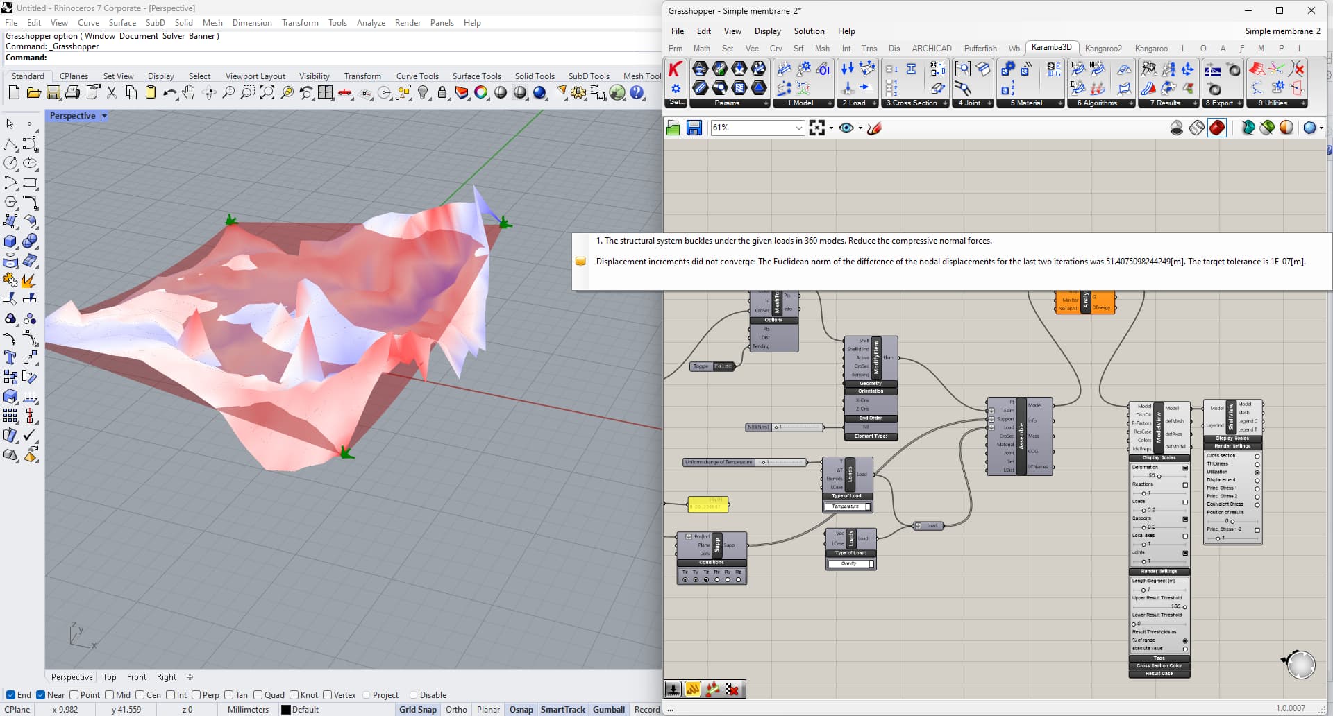
The structural system buckles under the given loads in 360 modes. Reduce the compressive normal forces.
Displacement increments did not converge: The Euclidean norm of the difference of the nodal displacements for the last two iterations was 51.4075098244249[m]. The target tolerance is 1E-07[m].
how could i solve? do you know a solution @johnharding ?
Hi,
you need to make sure to apply a negative initial axial strain to acheive the pretension in the member. Also your initial geometry fails because it is not a “formfound” membrane geometry. I have simplified your geometry to just 4 corner points and you can see that it calculates.
Well, membranes can only transfer tension… If the geometry you’re calculating has to transfer compression, it’s normal that calculation has difficulties to converge : there are just too much displacement and hence too much possibilities.
If we consider a structure like the one in the image below, assuming that the lines on the surface are non-deformable, to calculate the lowering of each area (the colored areas for example) I need to find the “formfind surface” generated by considering the lines on the surface as the border. So the white one have 3 boundaries, the blu 5 boundaries, the green 4 boundaries, etc. etc
could that be right?
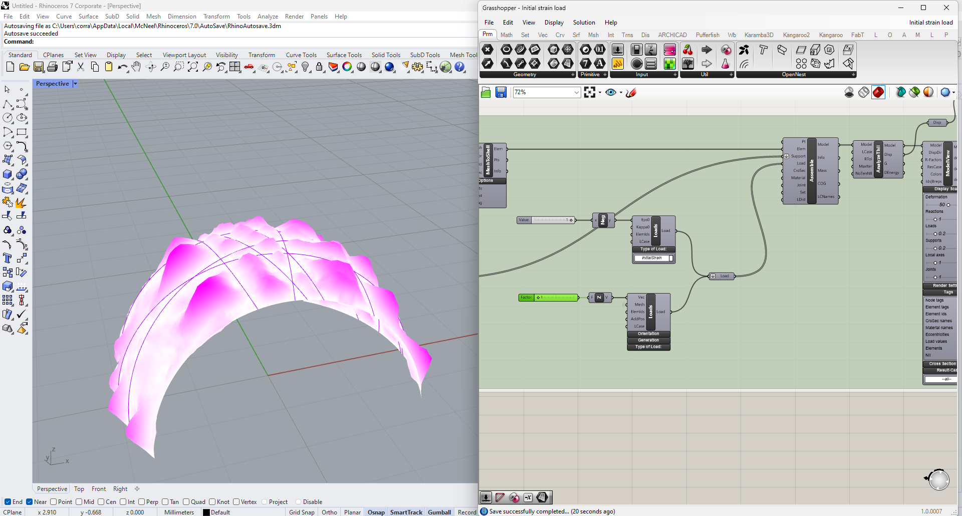
@matttam hello, I have a question for you about the “Initial Strain” load. Why does it generate this type of deformation outwards and not inwards?
If I increase the “Mesh load const” load, obviously the deformation goes back inward.
Is it correct to do it this way?
I’m very sorry to bother you, but you helped me a lot
The deformations seem to be correct. If you have a concave geometry under prestress, the member would want to deform back into its most planar (a convex) shape
Hi @matttam , sorry for all these questions. I am carrying out a university research on the geodesic gridshell. I would like to understand some results that do not seem consistent with reality and because I get these results.
These are some questions:
Considering the membrane of the first example. If the supports do not prevent rotations and the membrane has no bending strength, why do I get a deformation like the one in Fig.1 with non -converging deformations? Shouldn’t I get a deformation like the one in fig.2?
Is the maximum displacement that I get from the analysis components always a vertical shift on the Z axis, or does it represent the maximum distance between the initial point and the most deformed point?
If I apply a pretention of the membrane of a concave surface, this will tend to deform back into its most planar shape. By increasing the tension, the membrane should remain flat in accordance with the real phenomenon. Why does Karamba generate a deformation showing a convex geometry? shouldn’t happen in reality or am I wrong?
To find the “Form Finding” surface for the calculation of the membranes, starting from the initial geometry, can I use the “Large Deformation Analysis” tool of Karamba instead of Kangaroo2?
ad 1.) the initial geometry is not flat but has negative Gaussian curvature. This results in a slight upwards movement of some areas which looks wired when scaled up linearly like with the ModelView-component.
ad 2.) The maximum displacement which comes out of the Analyze-component is the largest absolute value of the considered displacement vectors.
ad 3.) Your system does not look stable. Did you check the Eigenvalues? Try to isolate one cell in a separate model to make it easier to find out what is going on.
ad 4.) The geometric non-linear analysis is currently (K3D Version 2) work in progress and does not converge reliably. You can try it out and it should lead to similar results like Kangaroo. There is an alternative in Karamba3D for form-finding (see here).
Hi @cp1
Thanks a lot for answering questions 1,2,4. However I still have some doubts about the 3. I isolate one cell to simplify the model and i obtain this result. The deformation appears to be the same albeit smaller. The system is actually not stable, how could I make it stable?
Hi @Corrado_Falato,
thanks for the reduced model.
How did you generate the initial surface? Is it an exact minimal surface?
I will check whether there is a bug in Karamba3D.
– Clemens
Hi @karamba3d to generate the minimum surface I used kangaroo, however the system does not seem stable. If you can check for bug and then update me I would be grateful
Setting the material’s lateral expansion coefficient to 0 slightly reduced the displacement under pre-strain.
The rest of the displacements can be explained by the fact that a membrane is not a soap skin. The geometry of the boundary causes a non-uniform stress-field with stress concentrations in some corners (see here: one cell_cp.gh (73.4 KB)). This results in transverse displacements of roughly 1mm.