First-time post for me. I’m looking for some help with a surface modelling problem I have. Usually, I can figure it out eventually but this one has me stuck…
I have two tubes with a small but constant gap between them. One tube is straight, the other is curved. The design intent is to have a flat surface to bridge the small gap, such that the flat surface touches each tube on a tangent, wherever that point is.
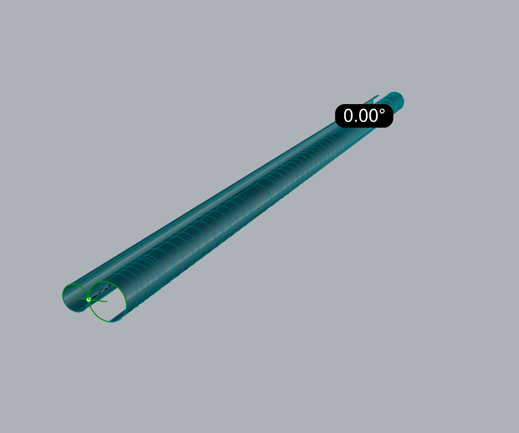
The problem appears easy in 2D - at any given cross-section, there are two perfect circles with a _Line_Tangent_2Curves between them. Hopefully the image below shows the problem.
Example file attached. I have made an approximate surface by literally taking many cross-sections of the pipes and doing _Line_Tangent_2Curves between each. However this is imperfect, un-matched and time-consuming to do, there must be a better way?
I have tried making a small surface and using _MatchSrf with OnSurface=On but this does not pull the surface to the tubes in the way I require. Maybe I am missing something…
I hope this makes sense, and thanks in advance for any help received!
The structure looks very good, better than I had achieved so far. Edge continuity is pretty close to zero, see image below. I think you are bang-on at the end nearest the origin, but you deviate at the far end from the tangent on the curved tube, but maybe just because it’s been matched or trimmed to the wrong curve at that end? See my layer “lofted_approx_tangent_surf”.
Geometrically, that can only be true for two tubes of constant diameter if the centreline of the curved tube follows a helix around the centreline of the straight one. In that case the edges of the bridge piece follow helices of the same pitch, so creating the surface is simple.
In your model, it does not look like the centreline is on a helical path, but rather in a plane, so the bridge piece cannot be constant width. Unfortunately the construction of the surface will be more difficult as a result.
Could you kindly confirm whether the intent is a constant width bridge or a non-helical centreline?
Thank you. The intent is that the bridge width changes, to remain tangent with both tubes.
The tube centrelines are parallel (366mm apart in this case) which does maintain a 1mm gap between them linearly (since tube radius is 215mm and 150mm) if that makes sense.
Hi Kelvin - if you know the top edge of the straight tube is correct, Sweep 1 the short line that is tangent to both circles along that edge to a similar line at the far end, using ‘Align to surface’ in the sweep. That will be tangent to the straight tube. MatchSrf to the other tube - it should be durn close as it is.
Thanks again. I don’t think this is right however, there is a reasonable difference between your surface and my “lofted_approx_tangent_surf” using 20+ cross-sections. The ‘bridge’ is also degree 3, so the surface has slight curvature. It really should be degree 1 and straight, with the edge positioned wherever necessary to tangentially match the tube surfaces.
In essence, this is a 3D version of the 2D command “_Line_Tangent_2Curves” which creates a degree 1 line between two curves at tangent points. I guess you could call it “_Plane_Tangent_2Surfaces”.
Any further help would be much appreciated, I am amazed there is no clean, easy solution given how easy this problem is in 2D.
nice problem.
your document-tolerances / units should be set to something that “matches” your desired result.
(currently meteres, 0.001 units, 1 degree)…
you can construct it with some basic geometric approach … all circles (2d) become pipes (3d) …
… what s the precision you need ?
… and what a pity - i changed the radis … to tired
That is the only way I know of if you want an accurate surface. Increase the number of lines to increase the number of curves.
Now for the complication. In 3D there is not a unique solution. So if you created the cross sections of the tubes with planes at different angles, found the tangent lines and then created a surface though those lines you would also obtain a valid but different surface.
I don’t know of anyway to determine the tangent location along either tube without determining the tangent surface.
this is my result - check the layer-names as a starting point.
→ copied everything to a new doc and set accuracy much to high / fine
→ build a pipe with R366 arround the line _pipe
→ _pull the curve to this pipe
→ the construction more or less is a 3d-adaptation of this
→ i would suggest to do this construction out of the bigger context, in a document with very small tolerances, copy back the result and maybe fit the surfaces to the needed Tolerance to have less complex geometry… depends a bit on your needs. tangent_between_tubes_TP.3dm (370.7 KB)
kind regards -tom
@Tom_P
In my mind, the tolerance was absolute, I assumed this could be done near perfectly (like in 2D). Otherwise, it should be 0.001mm and 0.1deg. It is a visible finished surface.
@davidcockey
Thanks. I don’t understand why it is not unique in 3D? The solution in 2D is unique, the cross-sections of the tubes can be extracted after the tube is defined.
@Tom_P
Thank you. I need to digest your solution tomorrow (late here), but my first thought is that I am expecting to see the width of the ‘bridge’ changing with the curve. Your bridge is parallel sided. Perhaps a more extreme relationship between the straight tube and curved tube would be easier to see what’s going on.
@pascal
I have not defined the top edge of the straight tube, this is defined by the surface I created using the tangent curves between the tube sections. I then trimmed the tube, but they do not match well.
Hi Kelvin - just to run through the process, I made a series of lines tangent to 12 circles - the result is pretty good, I think - .08, .02. The compromise I made was I extracted isos from each surface and pulled the ones on the curved tube to the planes of the ones oin the straight tube before making my tangent lines - they were a couple of thousandths out of plane.
How to make this more automatic I am not sure, it might be that a script could manage this if that degree of accuracy is sufficient, I’ll poke at it.
The 3D solution is unique once the normal directions of the planes used for the cross sections is defined.
To use this method each pair of cross sections which are to be connected by straight line need to be coplanar. For the tubes in this particular case it may be “close enough” to use pairs of circular cross sections of each tube though they are nor exactly coplanar. For a different set of tubes that approximation may not be appropriate.
I have been using _Section to extract the coplanar sections of each tube, resulting in two separate curves. True, the curved tube section is not a perfect circle, but it is a true section curve and therefore the straight-line connection to the tangent can be made successfully.
I realise now however that “_Line_Tangent_2Curves” asks the user to “Select curve near tangent point”. This is easy for the user to do in 2D, but hard in 3D. There are 4 possible tangent-to-tangent lines between two circles…
@pascal
I feel there is scope for a command to do this tricky ‘blend’, even if it’s limited to tubes or simple surfaces with only one or two possible tangent lines? The user would probably need to “select surface near the tangent” somehow to define where the blend is required. A script or command would then be able to build the surface to tolerance with minimum cross-sections.
If you loft between the two centrelines you gain a guide: on one cylinder the tangent is always above the lofted surface and the other below. More than that, you don’t need to be particularly precise.
Regards
Jeremy
An aside: It appears that the ratio of the length of a tangent line above that surface to its other part below may be constant. Need to test that with more variation between the tubes, but I’m wondering if there is a geometric solution buried in there…