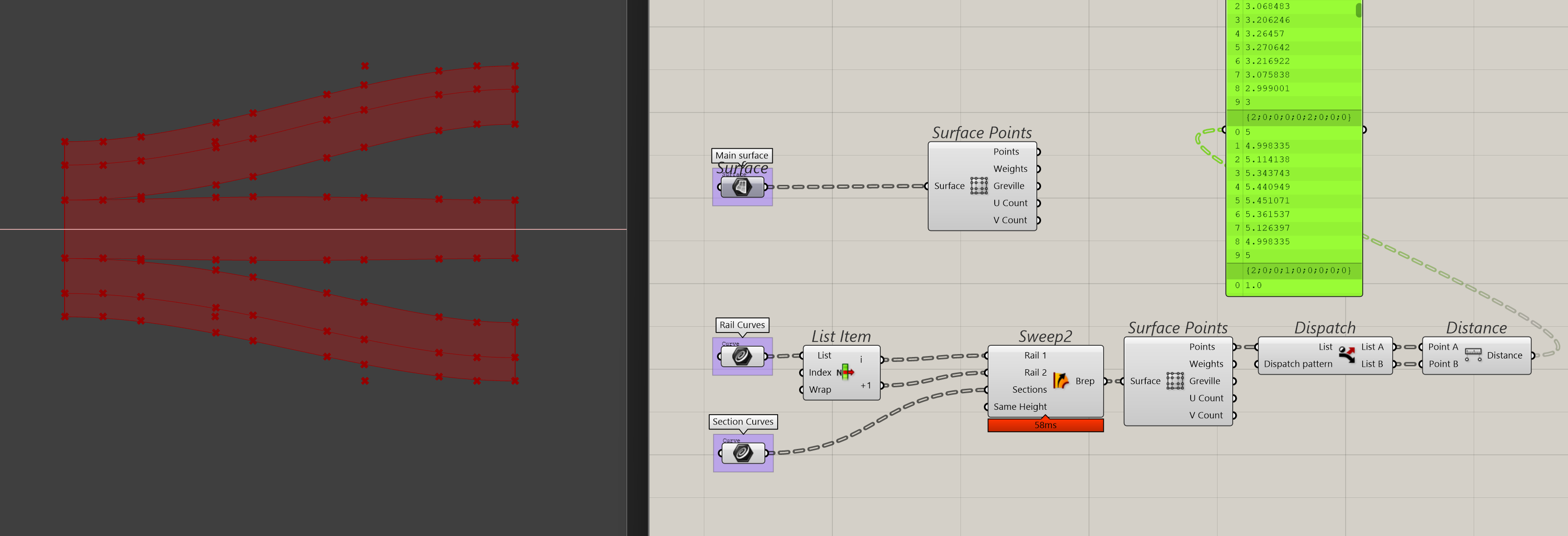
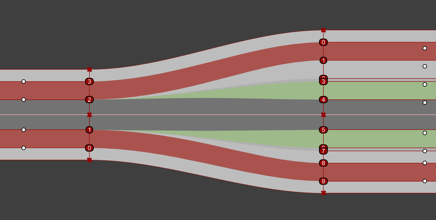
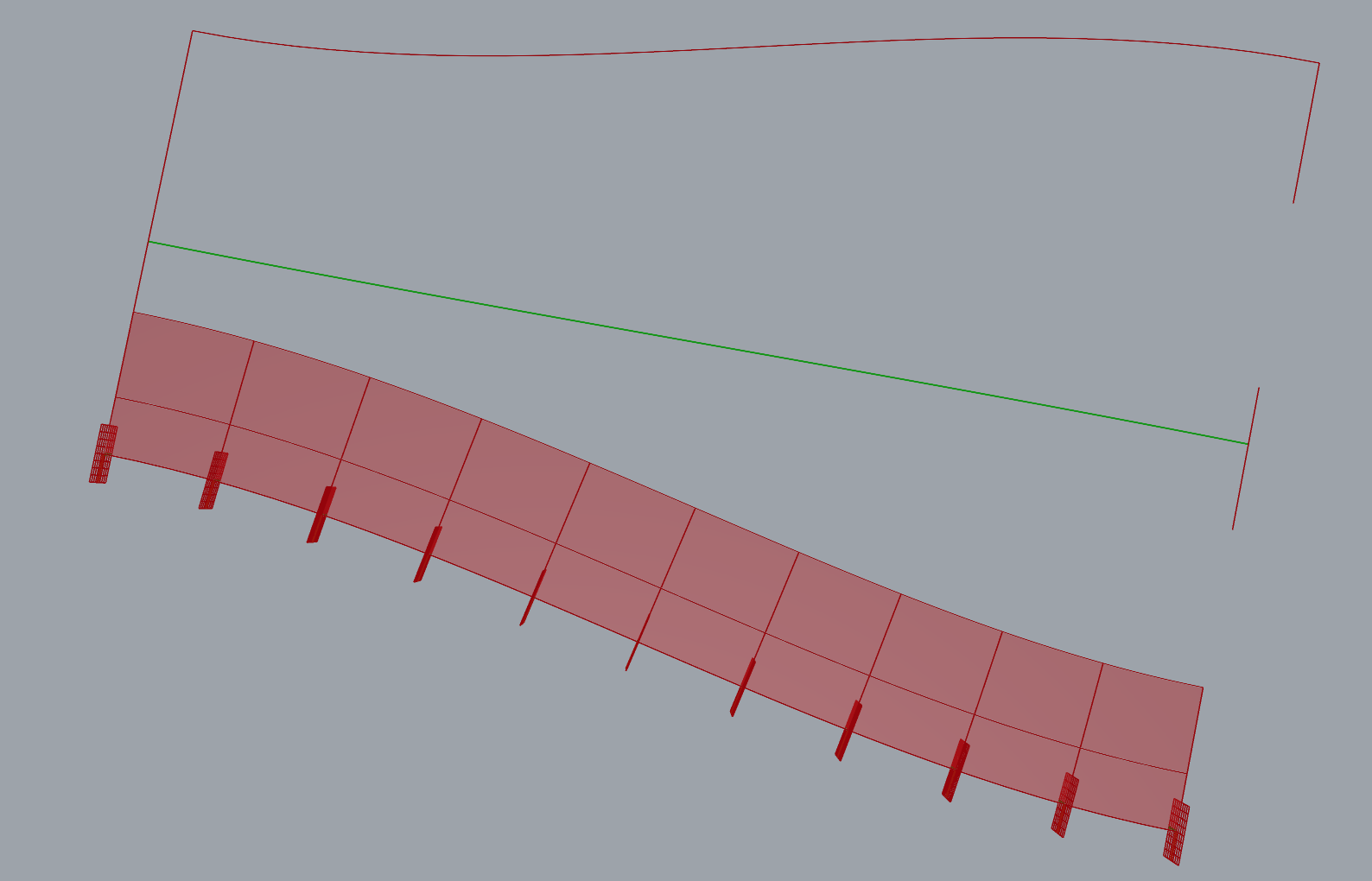
With the absence of a roadlike function for Sweep2, I’m looking to create additional sections at the surface’s CVs to help guide the sweep. The problem I’m running into is that I use the edges of the street as rails, but even when the section profiles at either end of the sweep are equal in length, it tends to diverge a lot around the center as indicated by the change in distance between the first (first section) and last pair of points (last section) in the list.
The surface is all wavy when I use both rails on either side (which I need to conform the swept surface to the street edges). You can see this numerically in the panel with the section distances.
It took me some time to understand what you are working on. For answers on this forum, best is to keep it simple. The faster you get an answer.
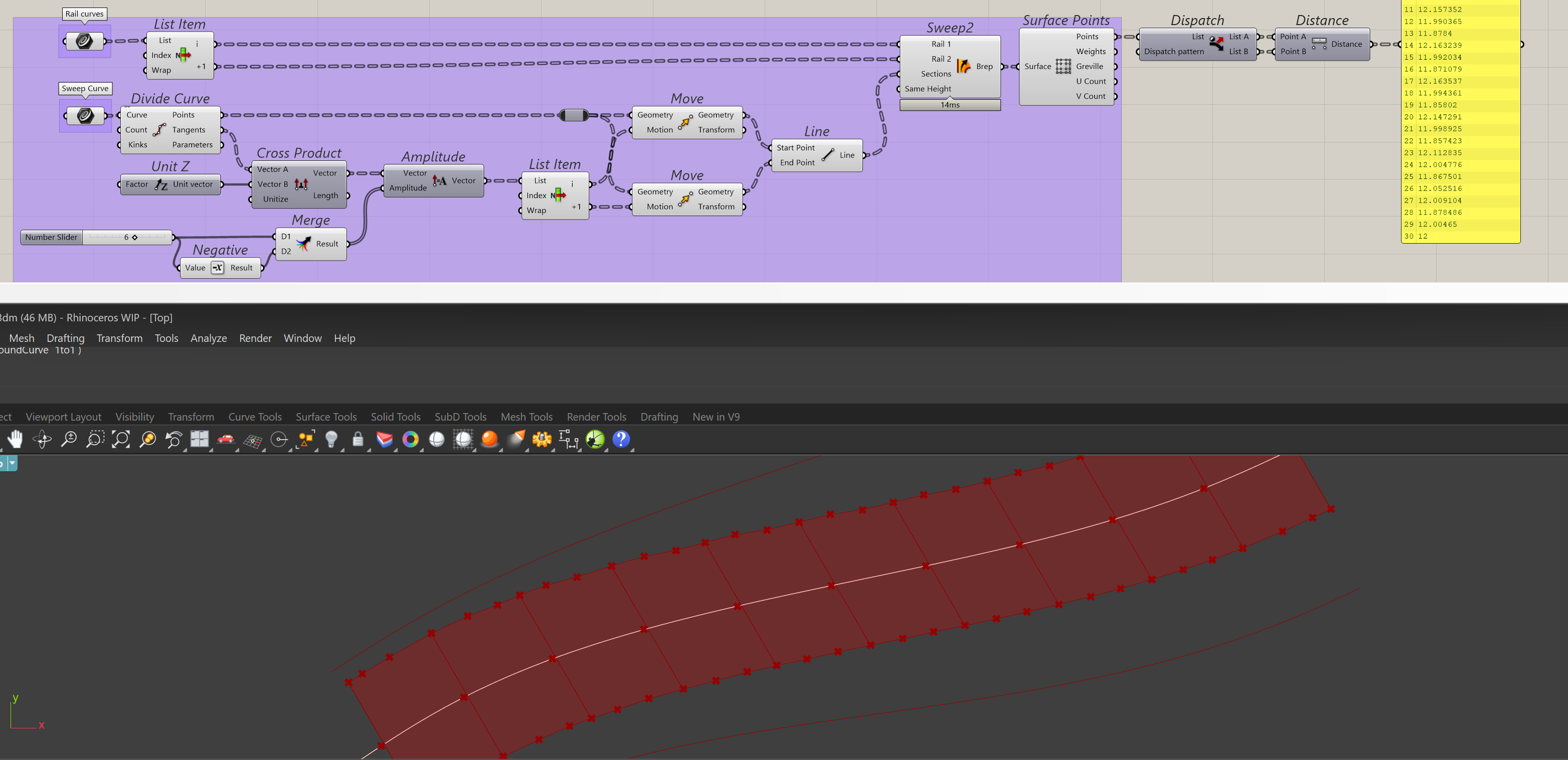
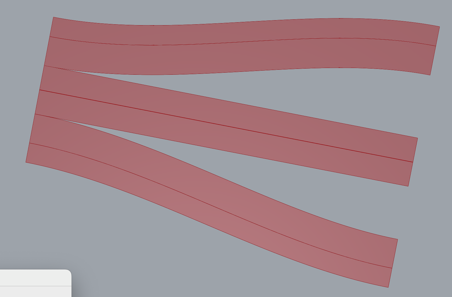
-For now, first I did was bring all your data back to one rail + two sections, together 1 road.
The problem with your approach (2 rails + all sections) is, that you force grasshopper to treat all these sections as parallels to each-other, giving strange effects in the curved parts.
Repeat for the other rail. (if you work correctly with the branches and lists, you could use the same components for that)
For the middle one, you need a new rail.
I would make that with Tween Curve (See the example I did. Also when the two rails you start with, are NOT symmetric, Tween Curve will create something in the middle.
Then you may use same logic as above (and could also be done with same components). Sweep2 RoadlikeEW.gh (19.3 KB)
OK. Something to study and extend for you. Have fun , regards, Eef
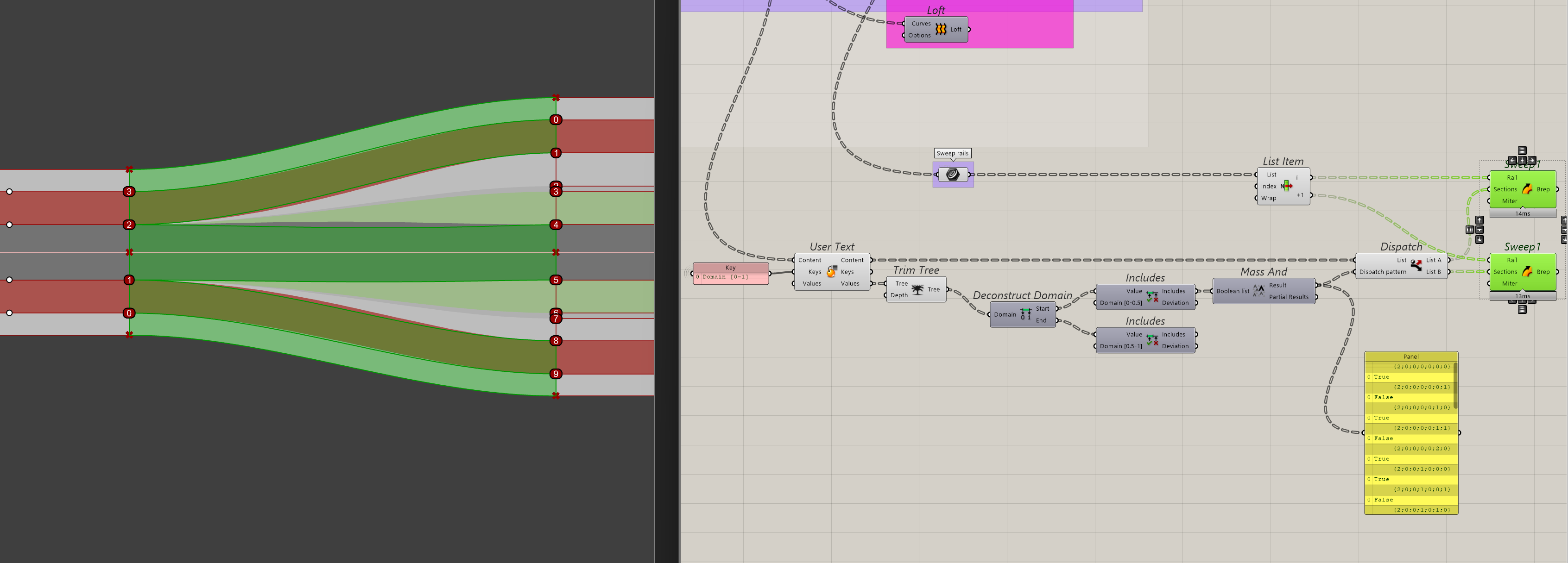
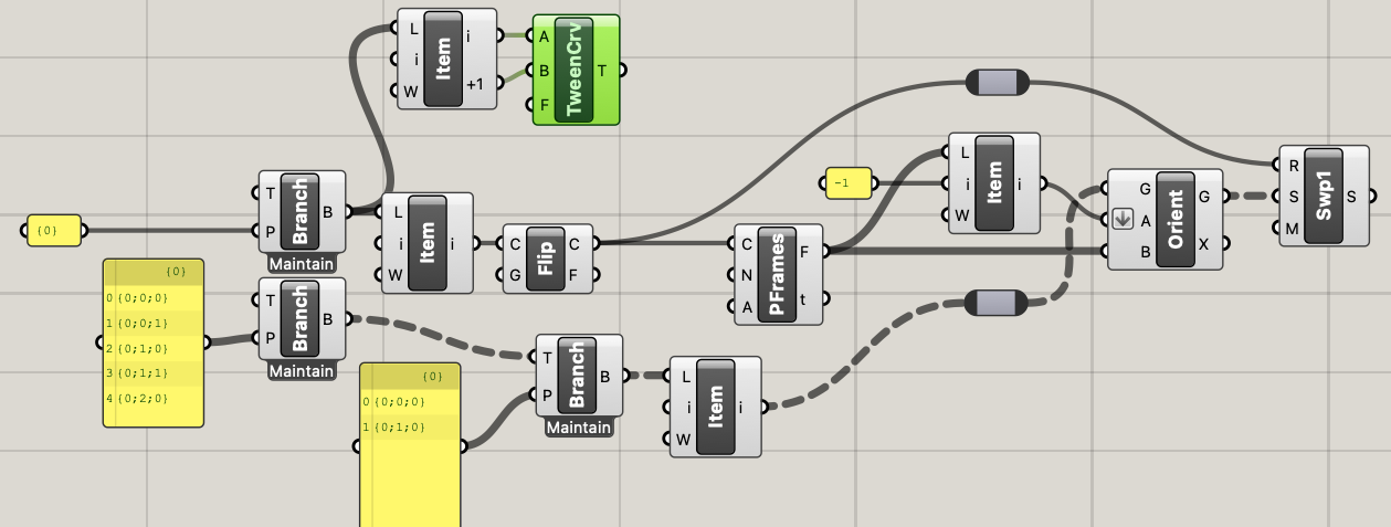
For sweep_1 those perpframes are not needed. I compared them, no difference to be seen. So kicked them out.
The middle one, was a bit strange, this is because these two sections may look parallel (as a rectangle), but weren a bit shifted. So I created a new rail with Middle Curve .
(I suppose for a road, that is not acceptable, if so, you need a new rail there (with a tiny S-curve in it).
The reason I started out with Sweep 2 rails is that I wanted to change the actual rails, so some could be G0, G1 or G2 matched with the adjacent road segments. With the lack of sweep options in Grasshopper, I can only get G0 and, G1 continuity on the rails with a loft or Sweep1 respectively. I only realised later that I can also re-use the rail curve I made the swept surface with initially with a sweep1. Doing so also retains the outer edges of the street, since the individual sections are made from the same logic (i.e. the sweep). In case I want a different kind of continuity match, I can make the initial surface with a loft and loft the individual sections later too. It’s just that that requires me to split up the data, but is easy to do.
The interpolation of different width and positions of the sections is what makes this hardest (i.e. transition from 4 to 6 meters width, while changing position relative to the edge of the street). Thanks for the help, I’ll study it and see if I may need to change my approach.
If you have a good solution for the middle curve (tween curve; curve middle line; or maybe something different.
You can turn this kind of solution into a user object what behaves more or less like a sweep 2.
Think of a new component (black box):
input 2 rails (the outer curves)
sections/segments.
Inner proces:
the two most close to rail 1 are used there and two others most close go to rail 2
section not used goes to the middle one
create new middle rail using distances to rail 1 + 2 (or middle curve) or something else, you take from the input.
sweep all three
Output: as you wished.
The interpolation of different width and positions of the sections is what makes this hardest (i.e. transition from 4 to 6 meters width, while changing position relative to the edge of the street).
Here you can use the perpframes, while giving each frame a gradually little longer section
I’m just curious here because this is not my domain: I understand why G2 continuity is desirable in product design, and I can intuit why it’s desirable in the XY plane for roads and railways to make smooth turnouts. But why does it matter for the cross-section curve? And is road construction technology even capable of matching a curve so precisely?
This is more for design aesthetics, it doesn’t have to be that precise. If it’s a near G2 curve, the tension on the curve looks already quite different from tangency. And for me, if the Sweep2 would support it, it would be a matter of changing a parameter from 1 to 2.
At least I got it to work as intended. I ended up splitting the data for a Loft or Sweep1 and did not bother with any interpolated sections. The Sweep1 made the dimensions within tolerance, so the street sections retain their width.