Sweep 1 self intersection artifact

You can split the swept brep twice, use shift list and solid union again…

The result subtracts just fine but leaves two internal seams.

As you can see in my file, I would generally use the orient component to to orient a section to whatever frame on the rail.

V-sweep1b.gh (22.0 KB)

2 Likes

Thank you for your help, Martin! This looks right to me - the internal seams are correct. I need some more time to fully understand why you need to split the brep twice (it didn’t work when I removed one of the splits). And why you need the shift list - (it still works if I bypass that).

Nice. I was thinking along similar lines but had to run an errand. I was trying to think of a way to make the split(s) automatic so it could handle arbitrary paths. I definitely agree about orienting the section curve to a perp frame at the start of the path. And I too made the section curve shorter so the sweep doesn’t intersect itself around the tight bend in the path.

I don’t understand either why two splits are necessary? But using only one cutter results in “Invalid Brep” or “Open Brep”, depending on where the split is done. :thinking: Your code works fine for me without the Shift List. Seems odd to me that the path curve isn’t planar since the cutter punched through the bottom at the very end of the path?

Interesting but mysterious.

Seems odd to me that the path curve isn’t planar…

I specifically want the cutter to be able to change depth along the path. That’s how the striped carving emulates the striped drawing. It punched through because I was careless (much less a problem in Grasshopper than in real life :slight_smile: ).

1 Like

OK, just be aware that making the path planar (projecting it to the XY plane) introduces potential problems of its own. I tried Sweep 2 earlier, using an offset curve for the second rail, but offset curve failed when the path was planar, intersecting itself.

I’d never used sweeps before and wasn’t sure how my section would orient with respect to the Z-axis as it travelled along the rail. Though I see the logic of using perp frames, that doesn’t match what my CNC can do. Since it is only 3-axis (and not 5), my cutting bit is always plumb to the machine XY axis. So keeping the sections parallel to the Z-axis is correct in this situation.

Sorry, I don’t understand that? Oh, do you mean that perp frames on a sloping path will not be aligned with Z? That makes sense. Still, I believe the section (cutter) should always be perpendicular to the path curve in top view. Otherwise the width of the cut will vary as the path curves, eh?

Still, I believe the section (cutter) should always be perpendicular to the path curve in top view. Otherwise the width of the cut will vary as the path curves, eh?

Yes - in this case, with a 90degree V bit, the width of the cut is exactly twice the depth of the cut:

1 Like

I have not tested the defintion above without the shift list. My thought was that I have to solid union in a specific order and I guessed that the two intersecting parts should be the first two items in the list. But it seems that’s not necessary.

The splitting can be automated by projecting the curve to the XY plane, dividing the closed segment and finding the two closest points on the original curve.

Below is a definition which uses horizontal planes so the sections are always vertical. I added two cones at the ends of the curve.

V-sweep1c.gh (30.6 KB)

2 Likes

Great thanks, Martin! I went through your solution, and every piece of it makes sense to me (a great educational example of components I haven’t used before). The only mystical bit is why the self intersection requires chopping into three pieces then recombining for it to work. But I glean from your and @Joseph_Oster’s comments that sometimes that’s just the way GH is.

2 Likes

Have you seen this discussion?

I guess so since I wrote that post. :wink: On my way out the door, back later.

@Joseph_Oster :slight_smile: This was meant for @Bruce_Shapiro

Yes - I linked to it in my opening of this thread. I recall trying @Joseph_Oster’s definition (using anemone) but IIRC also read about the multiple solid-diffs slowing things down. So I played with @RIL’s (further down the thread). But found it suffers from the same self-intersection artifact:

Oh I see your link to it now…

I created that definition with Anemone. Yes, sure it slows things down but depending on the requirements, this can still be an option. I’ve used it for CNC simulation a few times.

I just recently played around trying to create the loop with python instead of Anemone.

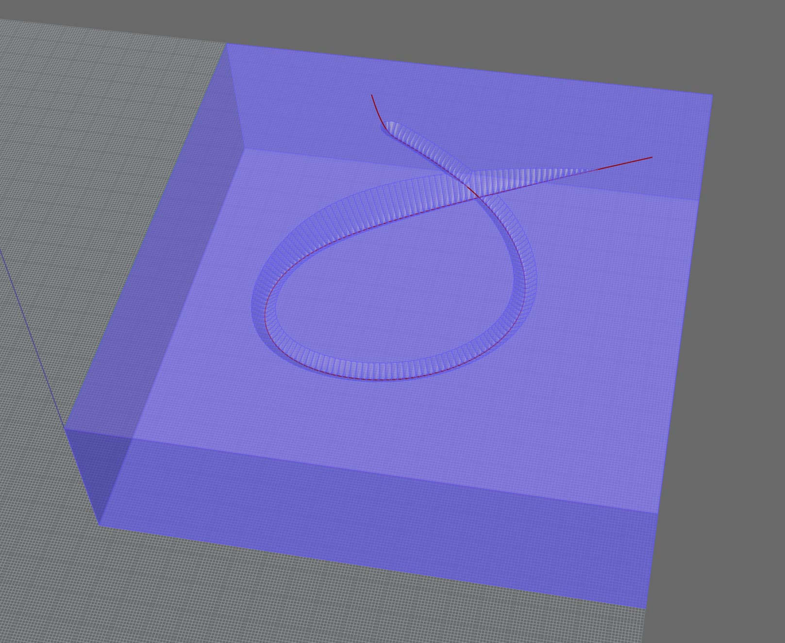
loop_while_python.gh (29.2 KB)

For this render I subtracted 500 cones in 2 minutes. I baked the result and sent it to Keyshot.

3 Likes

I’m looking for fast. Ever since childhood, I’ve always preferred a window seat on planes. Looking at the Earth, with all its amazing fractal terrains never gets old! I’d love to be able produce carvings like them, but not by using the “standard” method of milling topologic data in successive rows. I use Aspire for toolpath generation, and its visualizer is decent:


But I don’t yet have much intuition when it comes to predicting the carved result from fractal paths I feed it (and in this example the tool depth remains constant). I’m hoping for a visualizer that can work fast enough for me to tweak the toolpath and watch, in as close to real time as possible, for carved results I like. I suspect it’s a pipe dream, but GH has provided tools that approach this with my other algorithmic artwork (and it’s incredibly helpful).

1 Like

So how does Keyshot do it? Can’t be so difficult to create a cutaway material…

ShrinkWrap could be used instead of a boolean union of a mill bit at a few hundred positions…

engrave_wip.gh (29.1 KB)

Rendered in Keyshot with procedural wood and 0.5 mm radius:

Both Keyshot clue and ShrinkWrap idea are great. Really appreciate your help!

1 Like

There’s another option, however it feels a bit slow.

The engraved look can be simulated by adding a curve in the Shut Lining tab and the render mesh could be extracted…

It’s slower than my suggested approach with ShrinkWrap. Anyway, I think it would be nice to have a cutaway material in Rhino. Something similar to keyshot ideally :slight_smile:

I got a result with Radius = 8 and Pull curve to object deactivated but Rhino crashed when I increased the Radius to 10

1 Like