Heres one for you boat folks… A fading hull chine, and fading beltline fore/aft-
hint, I started with a side view “paper doll” and then pulled half the boat into shape before using mirror and join. Bonus if you get the fade from the front of the boat to the back on the top of the beltline.
nice! your is likely much more nautically accurate than mine!
As an exercise, try this… delete a few horizontal edges towards the nose of the boat that you used to make the crease, leaving some ngons… notice how it softens even more. Also notice how you may need to go into box mode and adjust for theose edges being gone to get your shape back… Always try to remove as much stuff as possible to get smoother results. If you delete something and it wrecks your shape irreparably, just undo and put them back!
That is my strategy too. For this model I added bevels around some edges, to fade the creases better and get some smaller radiï. That increased the amount of faces significantly, but these extra edges are also easy to remove.
The strategy to start with a minimum of faces would become a lot easier if adding edges in a simple SubD did not alter the shape. That is already on the list, hope it will soon be realised.
@theoutside I need help doing something like this. Can you explain what you mean by “delete a few horizontal edges towards the nose” ? Can you post a file that I can look at? Can you recommend any tutorials that I can watch?
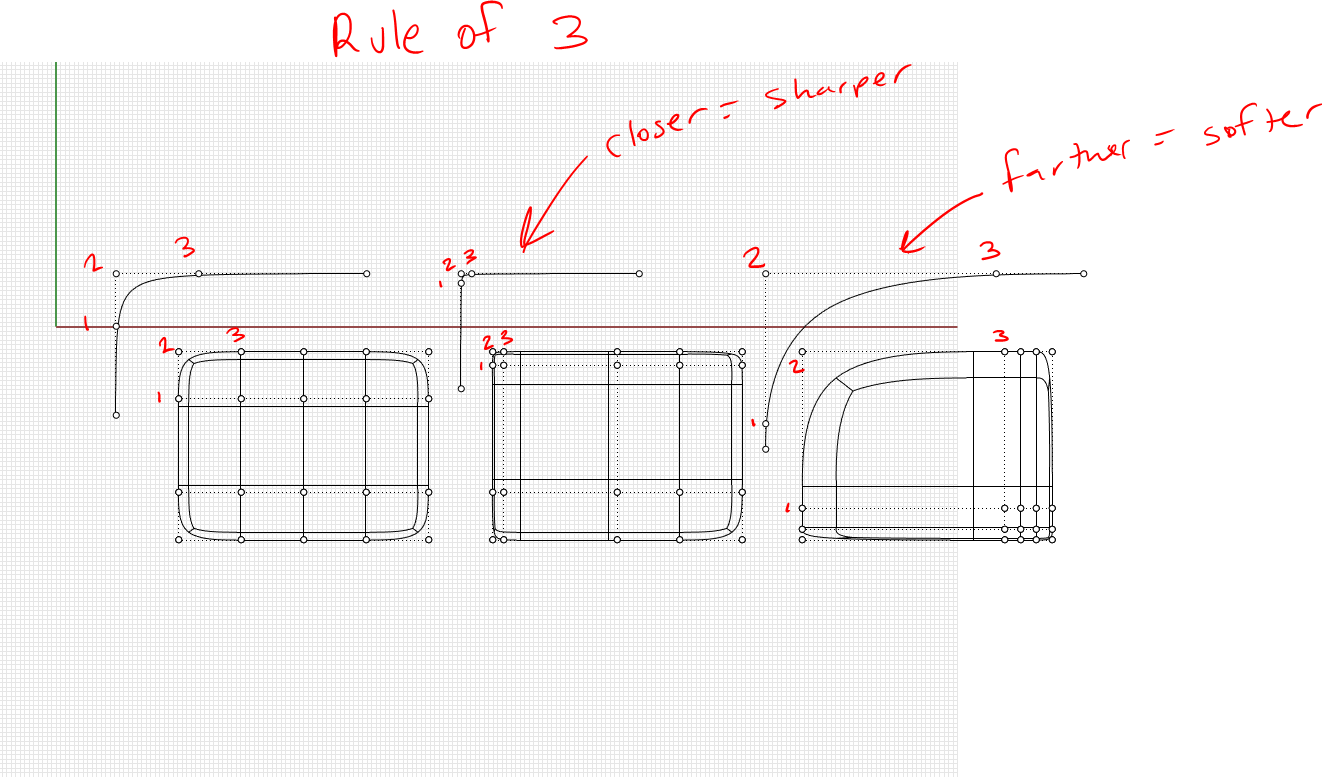
edge loops do not have to be continuous, and faces do not need to be 4 sided. You can add or remove edges, or more importantly, parts of edges to allow details to fade in or out-
Thank you. I believe you deleted a few edges towards the stern and left them in the nose. I can get something that replicates what you have done on the upper chines. I’m Interested in how you created the hull structure. The main chine is hard at the transom and fades into a smooth surface forward, but there are no edges missing. Also, there are no creases. I am guessing you created the hull with a sweep of 2 rails? And the hardness of the chine was defined by the section view?
in the one I posted, the chine fades because the 3 edges that make up the chine itself are closer together at the back and farther apart at the front.
Just like a nurbs curve, corners and features are defined by three points or three edges. In my videos I refer to this as “rule of three” It takes 3 points to make a nurbs curve corner, and as such takes 3 edges to make a subd corner.
Okay. I noticed that. It just seemed like the effect was greater than the difference in spacing, but I guess that was a wrong assumption.
I’ll watch the video to see if pick up any more.
I was able to get a pretty good surface with a Quad Remesh of a poly surface created with a few network surfaces, and some hand manipulations. The tough part is getting it down to a minimum number of control points to make fairing easier after creating the SubD structure for the feature line.
Some areas I need to learn more about: Soft transform. I would like to be able to have different radii for U and V not sure if that is possible. Also, I vaguely remember Orca3d had some good customs tool for projecting a series of points towards a curve or aligning them. I need to see if I can get those. Or make a grasshopper definition to do it myself.
50,000ft question; What would be your approach for trying to create hull form like the one below?
Is the face closest to the bow merged with the one below it or is that just a non-creased edge?
Are you sweeping a surface between the shear and chine or starting with a 6x2 grid and dragging control points?
There is concaveness in the panels forward and convexness in the ones aft. I’m having trouble fairing those because the isocurves are spread out and then crunched.
Also the window feature, are you suggesting that get trimmed in afterwards? It appears as though there is a variable chamfer around it. If that is incorporated into the SubD then the path that the isos have to take is more convoluted. I have found out to delete a face in a SubD to make a hole, but I haven’t figured out how to trim to an specific curve.
[quote=“fpagel01, post:13, topic:102164, full:true”]
Firstly, just want to say I apricate the help.
super happy to help-
Is the face closest to the bow merged with the one below it or is that just a non-creased edge?
Non creased edge
Are you sweeping a surface between the shear and chine or starting with a 6x2 grid and dragging control points?
i’m a point dragger, but you could certainly sweep a subd friendly curve-
There is concaveness in the panels forward and convexness in the ones aft. I’m having trouble fairing those because the isocurves are spread out and then crunched.
try using bend or cage edit for global shape changes like that-
Also the window feature, are you suggesting that get trimmed in afterwards? It appears as though there is a variable chamfer around it. If that is incorporated into the SubD then the path that the isos have to take is more convoluted. I have found out to delete a face in a SubD to make a hole, but I haven’t figured out how to trim to an specific curve.
100% trim those in later after converting to NURBS… keep a copy of your subd before you convert so you can make changes later if need be.
Give it a crack, and if you get stuck post the file, and I’ll be happy to help wherever useful.
Good starting layout strategy for that powerboat hull Kyle, maybe I’ll try my hand at such a hull since that sort of hull is maybe about half my workload these days. Even sailboat hulls are now incorporating hard chines and the window detailing for portlights in the hull like above needs sharp crisp hard creases as you show. I did a 50’ sailing catamaran using T-Splines that had both hulls and crossbeams as well as the deckhouse, cockpit and all window openings modeled in a single T-Splines surface. When converted to Nurbs polysurfaces it ended up with what I remember as hundreds of individual surfaces!
Design never got built but I did win a design competition for T-Splines though. I think you may have been a judge for that contest...
Definitely try this in SubD- Would love to hear about your experience doing so.
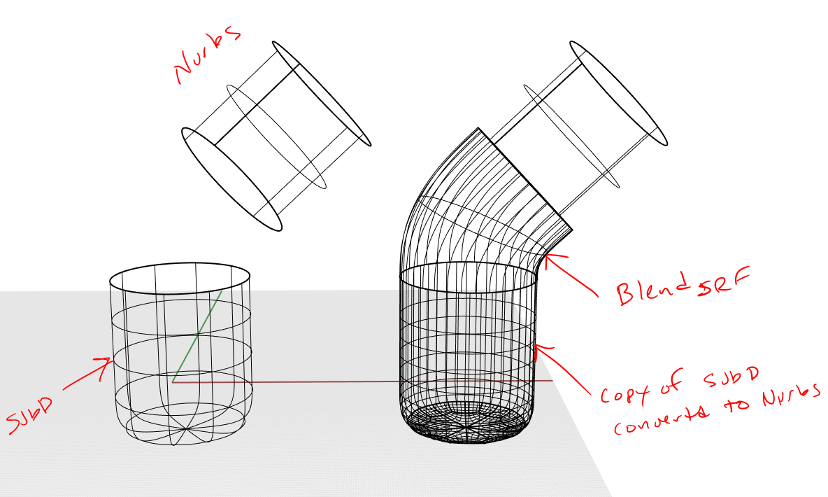
remember, use the right tool for the job… Subd for the swoopy bits, and nurbs for the sharp detailed bits, and a combo of both when appropriate.
Remember you can always use a blend surface between a converted subd and a nurbs obejct .
I will take a subd, convert tonurbs but keep the input object then run the blend, and then delete the converted nurbs object. That way I can keep the subd but transition into a nurbs object.
Ideally we could blend between a subd and nurbs without this sub step…hopefully in a future release.