Hi All,
I was wondering if there is an elegant way of filling out this type of corner. Basic tangency is good enough here. I’m not happy with my results.
Thanks
Corner.3dm (2.8 MB)
Hi All,
I was wondering if there is an elegant way of filling out this type of corner. Basic tangency is good enough here. I’m not happy with my results.
Thanks
Corner.3dm (2.8 MB)
Well, it is not really, you know, good surfacing, but Patch does a remarkably good job on this type of 6 sided thing.

Otherwise - not sure I love this but it might work- the red and green surfaces are not true fillets - they fudge a bit.
Corner_Maybe.3dm (231.7 KB)
-Pascal
Thanks Pascal for taking your time to look into it. Appreciate it.
Normally I don’t use patches as I have access to Rhino 5 and VSR. Didn’t have access yesterday so I tried recreate manually something VSR would have done in seconds and after several less than successful attempts I posted to the group. VSR won’t be available forever and Rhino is not coming up with multiple blends any time soon so better get my hands dirty and learn some basics…
Your Corner Maybe is a nice push in the new direction. Thank you.
Btw. Today with access to my VSR I build the corner in a blink. Good on first go without any further refinements. Long term, I’m not any better and still need to learn.
look for xnurbs.
Would be possible to see how xnurbs builds this corner…?
Thanks
6-sided corner.3dm (308.2 KB)
Usually I fill these 6-sided holes with 3 blend surfaces, with the last one being additionally modified to match the adjacent edges. Here is a quick tutorial that shows my approach. Keep in mind that I did it slower in order to be easier to understand and waited to show the tooltips on the icons I use. It’s relatively good for G2 modeling, though it could be used to G1 as well. Note that this approach is far from ideal and definitely not what a typical Class-A modeler would do with lots of time spent on manual point editing of either 2 or 6 4-sided “clean” surfaces. But it’s fast enough for my purposes, especially if the deadline is too close.
")
I also tried to fill your model’s 6-sided hole and it took me a bit longer to do so, because usually I work in millimeters and I had to try some extra settings in the “Match surface” menu, as your scene was most likely set to inches. Since your fillets are G1, the blend surface looks a bit unnatural overall, because its G2 is too smooth compared to the rest of the model. If the G2 smoothness is an issue for your application, you could use a “Blend surface” with G1 instead.
")
Corner.3dm (406.5 KB)
Hi Adam, Here is xnurbs corner as you asked.—Mark
Yet another approach, even though it tool unexpectedly long time, because Rhino failed to match the blend surface to one of the adjacent edges and I had to figure out what’s going on and how to fix that bug… ![]()
Maybe @Pascal should take a look at it, because this exact bug happens many times in random situations with no obvious reason.
6-sided corner 2.3dm (284.6 KB)
P.S.: The 4K video is still being processed but should appear soon.
Hi Bobi - some of the surfaces are rational- my guess is the ones that blends or matches that work less well involve those…?
-Pascal
your approach is good for this kind of 6-sided hole. bobi 
but pascal is right.
the match command is not efficient with rational surfaces.
it does not manage to position the control points
correctly.
but blendsrf works beautifully. with rational surfaces.
@AdamBBLee
can you share the solution you made with VSR. ?
i am really curious
just wanted to point out, that the topology shown here
is also possible with pure Rhino Commands
_splitEdge (Midpoints of hole)
build the inital star with
_blendCrv (edges)
_split (point) the curves close to the desired center
set a temporary c-plane and adjust the cvs of the curve with
_setPt
Build the inital 6 Surfaces with
_edgeSrf
optional _changeDegree U/V 5/5
a lot of _matchSrf “massage” … hopefully lucky
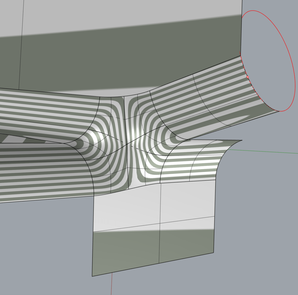
maybe also to mention that the dimension of Radius 0.1mm (red circle) might already be ambitious for the tolerance of 0.001mm
curious on the xnurbs result as well
Hi Pascal, as you can see in my video, I built two blend surfaces, then split them with two blend curves and then used the split edges of the blend surfaces as rails for the “Sweep 2 rails” command. Then at 3:19 of my last video above Rhino failed to match the edges of the swept surface to the split edge of the lower blend surface (it worked fine with the upper blend surface at 2:24, though).
The fix was to untrim the lower blend surface and then trim it again with the swept surface. You can see that at the 8:20 minute. Then at 8:49 Rhino was finally able to match the swept surface to the lower blend surface. 
Very nice job. I was using that approach in the past, but it takes a lot of time to play with the MoveUVN tool, so I rarely use it nowadays. And usually the end points shared between the 6 surfaces were not able to provide a smooth blending between them all, despite using “Set point”. This particular model here is a bit confusing to me as the tolerances and size are not typical for my modeling workflow and the settings I use on a daily basis were not working here.  Rhino had trouble with “Match surface” with very tight tolerances, considering that the radius of the original fillet surfaces is just 0,1 mm.
Thank you all for your help.
Mark, your xnurbs solution looks better than my VSR. Granted I only applied default multiblend without any further refinements. No more time for this project and in this case basics are perfectly fine. Is this something you did in one go or after several iterations…? I’m interested because I often get projects that require moderately complex surfacing yet offer little pay so I need to get them out of the door as efficiently as possible.
Bobi, what can I say. It looks fantastic. I’m still trying to wrap my head around it. So more advanced from what I’m accustomed to. Bookmarked your videos and will watch them again… few more times. Hopefully improving my skills just for my own sake because doing it this way in real life would kill my scheduling due to time required.
Tom, that what I was trying to accomplish myself but after 3 or 4 not too successful attempts and, again, pressed on time I moved on. As for the units this is what I normally have them set to. Should I be more flexible here…? This part is indeed very small. Around 20 x 20 x 15 mm.
Fares, file attached. Corner.3dm (2.9 MB)
Yes , I used it without adjusting anything. I think there are available adjustments if needed.—-Mark
Maybe that simplified tutorial will be easier to understand? ![]()
Keep in mind that after building the two “Blend surfaces”, it’s recommended to check and verify if their upper (a) and lower (b) edges properly match the adjacent surface edges, because the “Blend surface” tool originally only matches the opposite ends.
you ll find a lot of infos about tolerances in other threads and for example here:
My rule of thumb: with each further step after modelling you will loose one digit.
For Example:
if you target a 0.01mm production tolerance, the g-code for the milling machine will be rounded to 0.001mm and the modelling should offer 0.0001mm
If you do a Fillet / Radius with 0.1mm i assume you target a production-accuracy that is 0.01 or less
And if your Object’s dimension is within x,y,z +/-100mm (close to origin) i would not expect problems with 0.0001 or even 0.00001 mm absolute tolerance.
check the link above for more information.
kind regards -tom
It’s good to know. Thanks Mark.
Bobi, I have no problem following your video tutorials. Only when I do my own fillets I usually end up with surfaces that not always meet my expectations. I guess I need more experience with matching techniques and point manipulation.
Tom, since I model parts in small scales and in need of tight fitting .001 has been working good. This particular piece is for injection molding and a part of assembly. Sorry, can’t say more, my client asked to keep my mouth shut…
The only issue is when I switch to larger parts but keep same tolerances. I might revise this in the future. Thanks for the link.
Of all the super useful functions of VSR/Autodesk’s plugin “multiblend” Is the one I see virtually no good use in Rhino for.
It hardly works even under optimal conditions and is by no means a tool to create high quality surfaces (which is the whole point of the plug-in)
Give me shape modeling’s blend controls, surface matching, extend surface, explicit surface controls, cv controls with falloffs and its continuity analysis and I will cry tears of joy (figure of speech), but who gives a feck about multiblend and why?