Spiral inside loft.gh (81.3 KB)
Hey guys,
Tried looking for a thread that solves this problem but couldn’t find it.
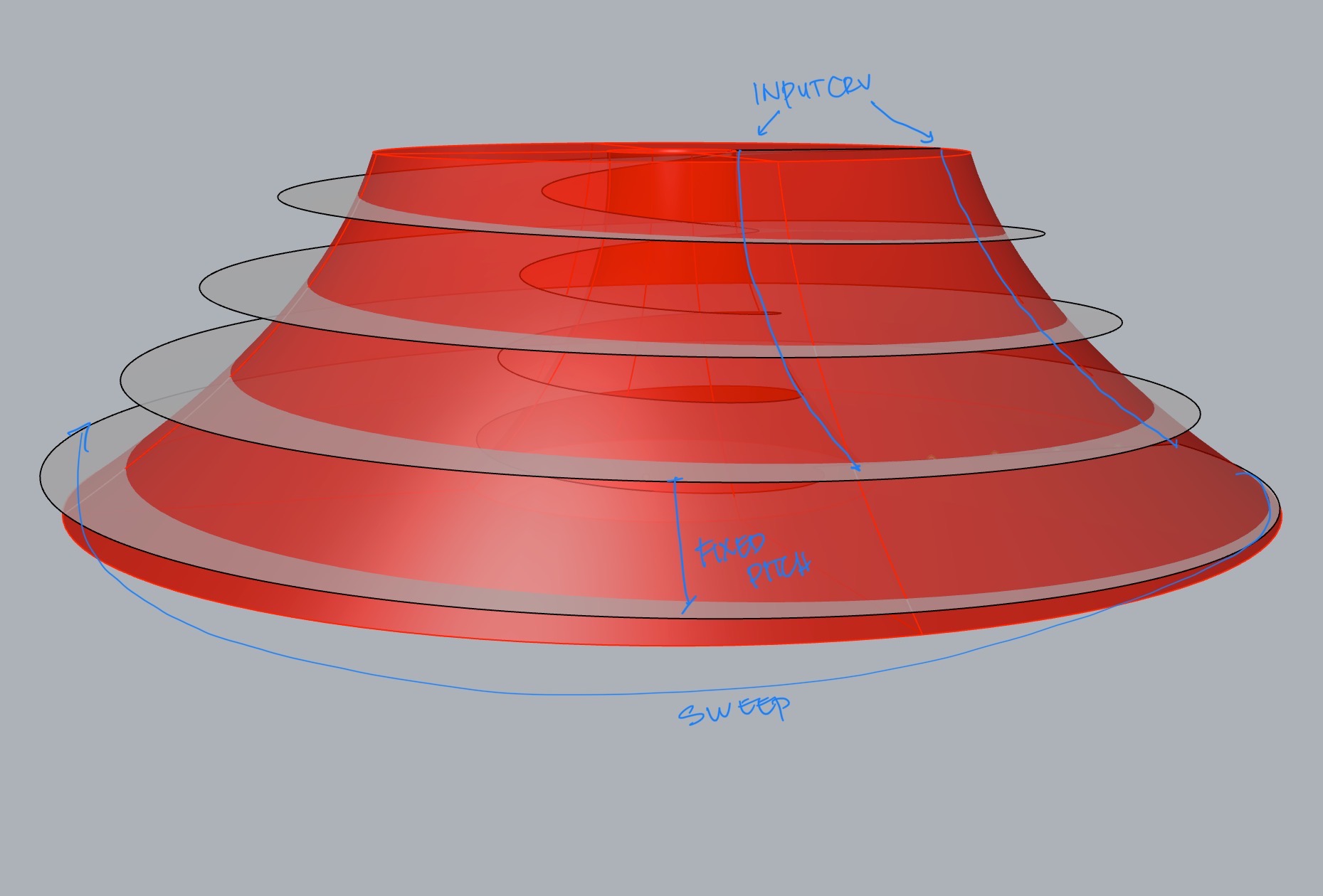
I’m trying to design a tapering spiral surface with a fixed pitch that fit within the boundary of the loft.(which is sweeped to form a closed boundary)
Alternatively, Is there a better way to make a tapering spiral surface that can be controlled with a bezier crv (graph mapper)?
Thanks for the Script, However this still does not give me control over the overall profile on the boundary. Ideally I’d like to control the curvature of the boundary.
Thank you Joseph, I’m facing a similar problem with this script as well where i’m not able to manipulate the profile of the inner cone. I would also need to control the outer boundary. I tried pull to srf. But it’s not accurate. The global bending of the spiral is lost when I do that.
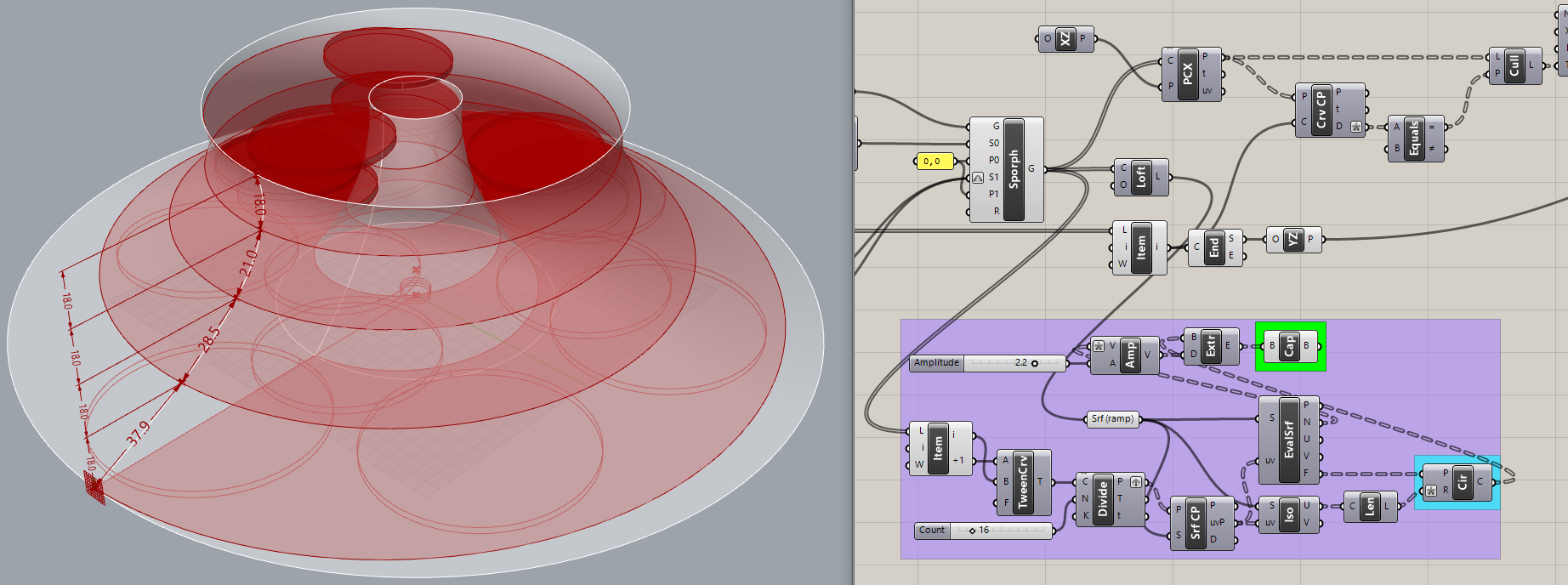
Yes, it’s unfortunate that a center point is not defined and the two curves are not parametric. I replaced loft/sweep with RevSrf(yellow group).
I adapted code from the first link I posted. The ramp shown is the maximum slope allowed by ADA standards. The ‘Rise’ and ‘Run’ numbers also affect the precision of this model, as you can see by enabling preview of the PLine component before Loft. Decreasing the ‘Rise’ value will decrease the slope and make more turns.
Additionally I’m trying to add circles to the surface without intersecting. I tried to unroll the surface to get a strip and then populate with reducing diameter and flow alongsrf. But it doesnt seem to work. spiral_inside_revolution_Circles_01.gh (21.6 KB)
Yes, I think so. The lines you were using were not “square” to the midline of the ramp so I re-wrote your purple group, making circles using surface frames so they are “flat” on the ramp. Then I extruded them and used them to cut holes in the ramp - which I realize now is not what you want? Very easily changed, I’ll post both versions. I added an expression to the Circle ‘R’ (radius) input to use only 0.85 of the ramp width at each point, so they don’t touch the edges.
I’ve used Sporph before but believe the method I posted this morning is better for this. What is this thing anyway? Very strange.
In the process of getting version ‘b’ (below), I just realized that surface normals of the ramp are pointing down instead of up. Probably a result of the sequence of spiral curves going into Loft. Yep, adding ‘Reverse’ at the Loft input makes these extruded disks go the other way.
P.S. Adding these disks to my earlier version ‘a’ was a bit more troublesome than I expected. You will have to decide which one of these horses you want to ride.
Srf CP to get uv for Isotrim. That’s smart! Learned another new thing haha!
It’s definitely version b that’s what I want. But I want to populate as many circles as possible using the max width of the ramp without intersecting. It’s in a way similar to Doyle spiral. Does that make sense?
I adjusted the expression .85x to .99x and increased the number of divisions but then the circles are colliding.
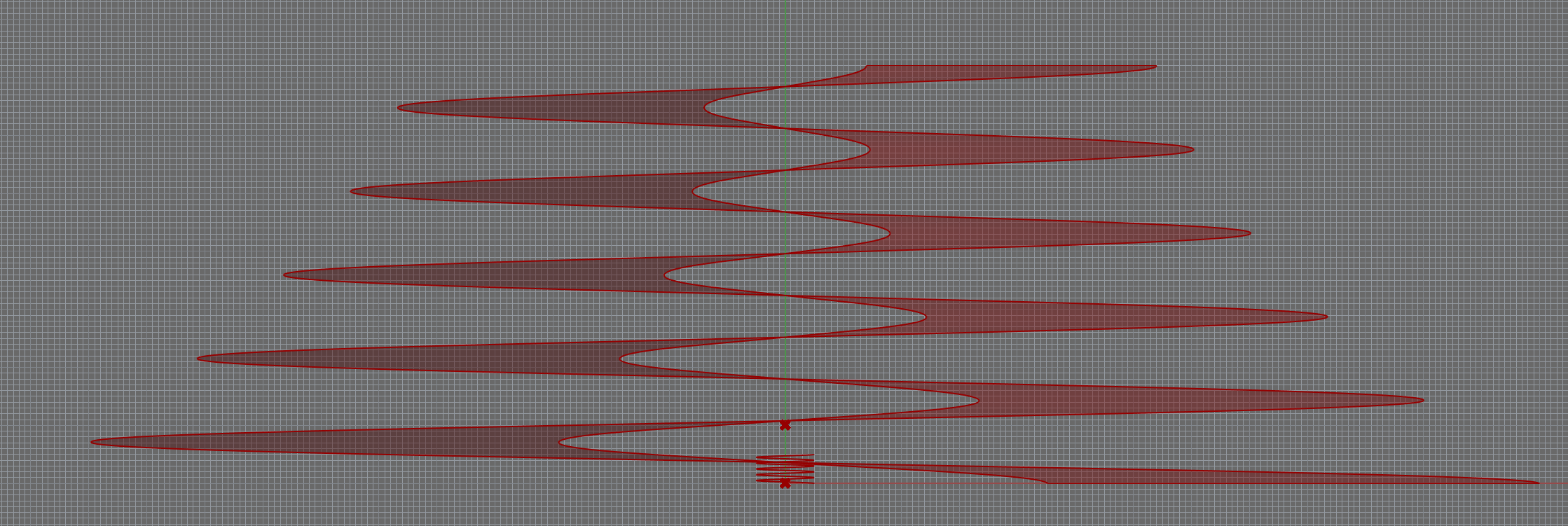
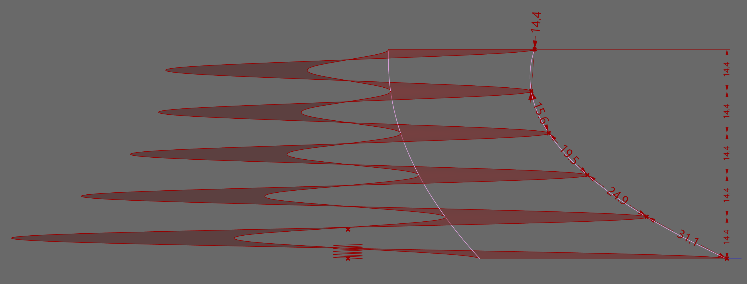
Maybe I’m not using the right words but what I wanted to point out is that my approach with the sporphed spirals results in equal height difference and increasing slope while your loft has an equal slope but the height of the loops decreases.
Yes, it’s the difference between architecture and art project. In architecture, constant slope is important for ramps and stairs. The circular disks make it clear to me that this is an art project. Unless the RevSrf is transparent, most of the disks will be hidden, eh?
Yes, The thread talks about exactly this topic. I found a python script in this thread that solves the problem, But it stops at 6 circles and does not seem to follow through all the way to the top. Anyway to fix this?
This solves it perfectly. Let me see where this leads me.
Meanwhile, Could you explain what you have done with anemone in the lower part of the script. I tried to break it down but a little confused on the logic process.
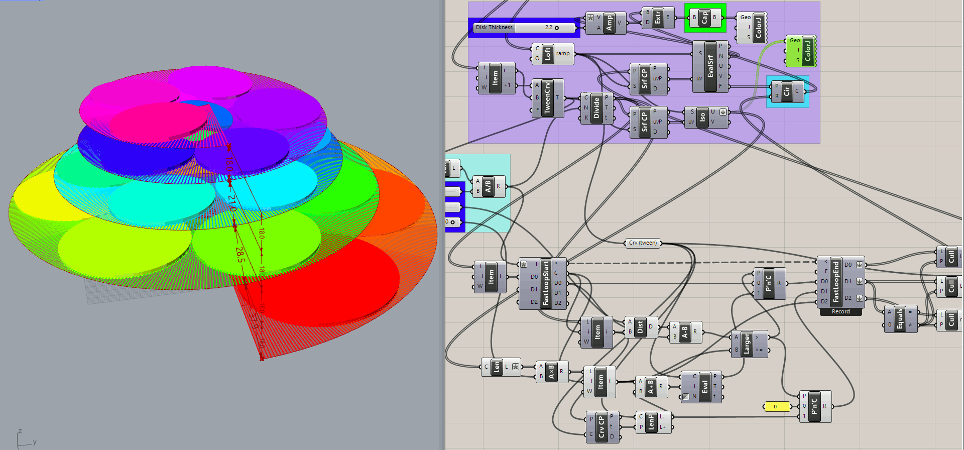
Enable the second ColorJ component in the purple group, just above Circle. Those are the isocurves created prior to the loop, which uses their lengths (divided by two times the %Radius value) and the Divide points on the tween centerline of the ramp. The Anemone loop counter uses each of these values, one at a time, to determine when the distance from ‘D0’ (the previous point) is Larger than the radius value at that point. When True, the two P’n’C(Pick and Choose) components use their ‘1’ inputs instead of their ‘0’ inputs for the ‘D0’ and ‘D1’ inputs to FastLoopEnd.
When the loop is done, each of the outputs has the same number of values as the Divide points. The ‘D1’ values are all zero except for the non-zero length values, which are used to cull all three outputs. Culled ‘D1’ and ‘D2’ are passed back to the purple group as ‘pCircle’ points (from LenP) and ‘radiusCircle’ values to create the disks.