I’ve been trying to boost my surfacing skills but got stuck. I cannot seem to get a nice transition between two surfaces and I’m starting to wonder if it is geometrically impossible so I figured I’d ask the surface experts here.
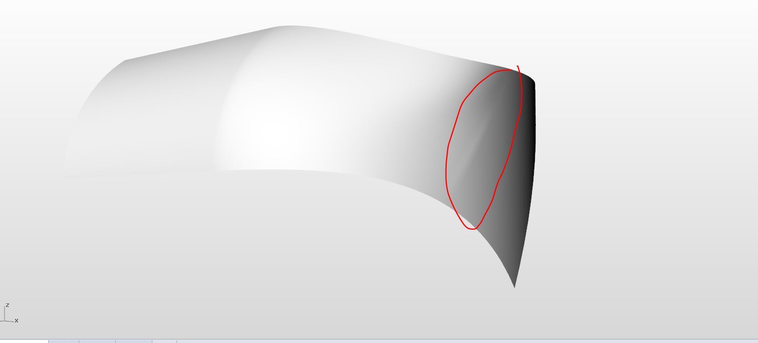
So I get this problem when trying to blend the surface on the right to the surface on the left using sweep2.
This is what I’m trying to achieve when it comes to surface requirements. The bottom curve of the surface to be created needs to stay like that, the top one can be modified a bit.
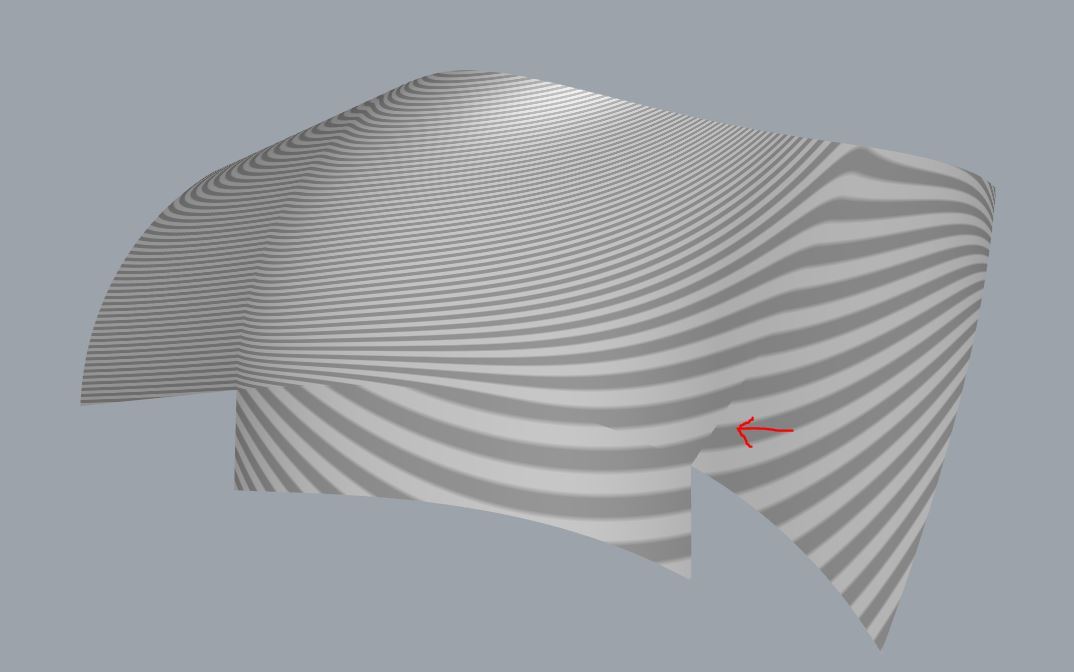
When you use zebra stipes on it , do they look like continuity correct? If so, perhaps it is one of those times when surface point adjustment is all you can do(manually) to soften it a bit. If those surfaces were made of a sandable material, wouldn’t you try and mellow that ridge down with sandpaper until you were satisfied without loosing too much of the whole surface ? Hope someone can help besides my explanation.—Mark
Sorry I don’t have much time to devote to this as I have a deadline. Take a look at the attached model.
You may not be able to make it exactly without creating the same surface you already have.
Tricks = use the edge and pipe command - split surfaces and then use blendsrf with either tangency or curvature to iron out some of the poor transitions
Use curve network to create a base surface and then extend surface edges - use other curves to pull pack to the surface and trim.
It should give you some ideas as to how to work with what you’ve got.
The curves connecting the two surfaces are only G1 (tangent) continuous with the surface edges. Without modifying both curves it will be impossible to obtain G2 (curvature) continuity with the surfaces.
Thanks for that, that’s really helpful. It’s never occurred to me in the past to change the degree other than rebuild. You learn something new every day.
If you were responding to my post:[quote=“davidcockey, post:7, topic:35449, full:true”]
The curves connecting the two surfaces are only G1 (tangent) continuous with the surface edges. Without modifying both curves it will be impossible to obtain G2 (curvature) continuity with the surfaces.
[/quote] the G1 continuity rather than G2 continuity of the curves with the surfaces has nothing to do with the degree of the curves. The ones in siemen’s file are degree 5 with lots of control points so G2 continuity is possible without changing the degree of the curves or adding control points.
For the best continuity possible the rule is to keep it simple, the lowest degree and points that represent the shape, besier patches are great for this.Try to use the same structure for the surface that you want to blend, this way the control poins travel from one edge to the other fluently with the same number of points. Avoid trimmed edges whenever you can if the shape give you the chance.
I’m not sure if this is what you need exactly, but it’s a good start.
Andy, just to be clear, the ‘G’ designation is used to indicate continuity (G0 = position, G1 = tangency etc) , not curve or surface degree, which is a different thing altogether.
That’s looking pretty good! Although when I put the horizontal zebra on, there still seems to be a sharp edge. Also when I try to render it I get this sharp edge.
Yes, there is no perfect solution for this case. You requested a vertical
tangency in the bottom that is forcing the form and doesn’t let you match
exactly smooth to the other sides.
The “sharp edge” which the red arrow is pointing to is probably caused by the tangency rather than curvature continuity between the existing fixed curve used to generate the surface and the exist surface. You will need to either alter the existing curve and/or existing surface to have curvature continuity, or accept the soft edge. That’s due to the geometry, not limitations in Rhino.
I’m catching up… But doesn’t this surface perform the correct function? It’s using the same curve edges and the deviation isn’t too far out except from the point where the unwanted bulge is…
remove the bulge
create a flowing surface
(I understand that it’s not answering the original question about the transition with blend etc as I’ve rebuilt it from the driving curves)