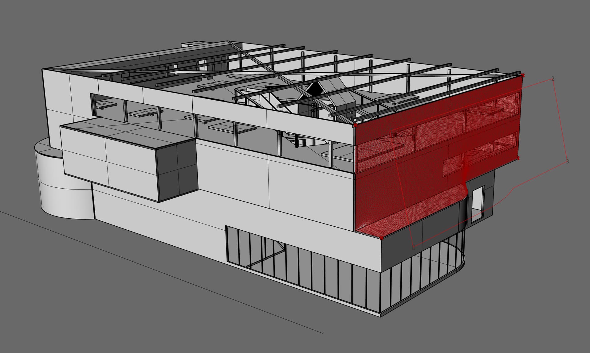
Your Rhino file is missing a boundary for the mesh. I think in the real world you would tie a mesh to a rigid boundary. Most probably the simulation can be achieved without collision detetction, if the boundary is on the edges of the building.
Here’s how I would do it if a triangulated mesh is sufficient for this project:
Define the boundary curve on the building. Set the curve seam to a corner of this curve and set four corners for this curve in the Grasshopper definition. The order of the points needs to match with the curve direction.
Project the curve onto a plane outside of the building. This projected, planar curve has the same topology as the original curve. The plane for the projection needs to be chosen so the projected curve does not have any self intersections and does not loose any segments.
Start with a less defined mesh until you know the definition works fine. Then lower the Length value on the triangulation.
PS: the right side of my example does not have any curvature in it. I think I’d try to have a boundary that creates more 3D than what is currently shown.
Hey Martin
Thanks so much for your help on this. Unfortunately my grasshopper skills are very minimal and so figuring out how to set this up is really difficult. Below I have attached just a single object that is my building and I was wondering if you could explain how to use the codes above for using a sinlge Brep to define this shrinkwrap
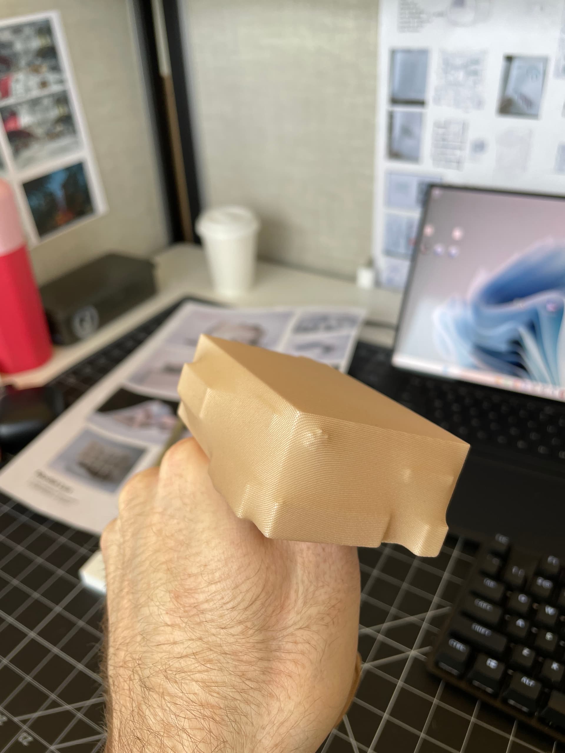
That makes sense. I have attached a new fixed model and photos of what I am going for below. One photo is a 3d print i made and wrapped in a stocking which is the look of what I am going for. As well as the photos I added. The faces of the extruded boxes will be glazing, but i just am looking for the edges of the extrusions to be sharp. FIXED EDGES.3dm (395.9 KB)
The first one is remeshing your object with TriRemesh so it has colinear edges like your polysurface. This failed at the real size of your building and I needed to scale it down to get it to work.
The vertices on the outermost convex edges can be set as anchors. In theory a net would also slide over those edges… The top and bottom side of the mesh can be ignored to save some time.
We’d be done, if it wasn’t for the collisions. In order to have a somewhat useful result, the mesh and the collider need to be relatively dense meshes, otherwise the edges aren’t crisp. It would be easier if the collider was a sphere. The denser the mesh, the more precise is the result but also the longer it takes.
I get the best result by moving the collider solid incrementally towards its final position. In this case I scaled it from 0.96 to 1 in 0.002 incremets with a slider. I changed the slider value with a keyboard shortcut. After having done this twice, I realized I could use a counter that I think Daniel Piker posted a while ago. It needs to be stopped manually but it’s still a lot bettr than pressing a button repetively.
I also increased the mesh density. The star shape is still problematic.
This is literally perfect wow! This is exactly what I was looking for. Is there anyway you could post the baked model? I dont really need to change it at all!
oh yes, it was hidden away from the main building at the constrcution plane. You have saved my project!! thank you much Martin you really were so helpful
Not sure, your object orientation differs from the last file.
I placed it with what I assume is the underside on the XY plane, scaled it down and I’m also using a millimeters template with 0.001 units tolerance in contrast to your 0.01. I also added a hexagonal shape on top of your asterisk shaped logo.