Good Morning, I need some help about my girder bridge example.
I think it’s all good about the assemble model part, with correct collaboration beetween beams and shell, but I can’t understand the results about shell forces.
When I analyze the upper stage of the shell, as the deformation, there is compression stress, and obviously, the lower stage had tension stress. So, Why the shell forces component, gave me a lot of Normal Forces value (KN/m) > 0 (Tensile stress) larger in number and entity then the compression one?
In addition, if I flatten the normal forces value in output of the component, I obtain larger value in entity then the same not flatten. Why it happen? What’s the value I’ve to consider for my analysis?
Thank you in advance.
Leonardo
Dear Leonardo,
it is hard to judge what might be the problem without the Grasshopper definition. Could you provide a simplified, scaled down example?
Best,
Clemens
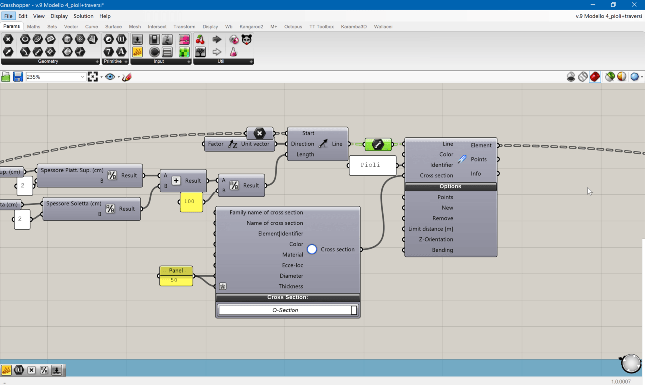
Sure, Clemens. I’ts attached a simplified shell structures like it’s in my model but without the stell beam. Anyway, I’ve to verify the shell and I need to extract the stress of the top surface of the shell along the transverse direction (x). I see it’s possible to extract principal stresses, but these are not directed as the global axis of the model, so I decide to try with the local value from shell force component, like mxx,myy and other parameters like vx,vy, ecc…
Now, when you change the U,V count of the 3 meshes in the model, this local value drastically change. For example, vy value change from 10/20 for little discretization, to thousand value for 30 discretization.
I’ve to keep an high value of U,V count because I need a sufficient number of connection points with the lower steel beams, but I don’t understand which value of mxx,myy,vx,vy I’ve to choose for my analysis.
Hope you can help me,
Thank you in advance.
Leonardo
Local Shell Value.gh (25.5 KB)
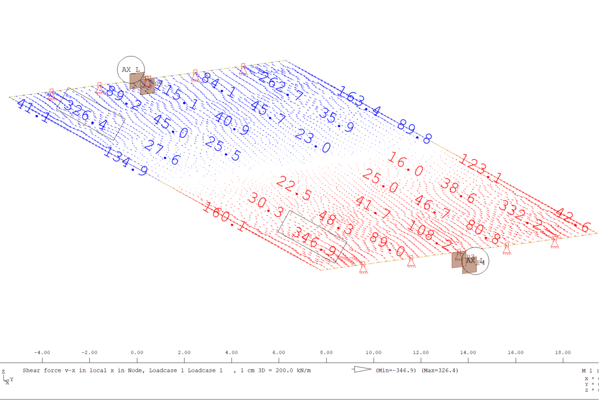
Update: I’ve verified as much as I can the result for various mesh possibility and here te results I obtained for the attached model: for a simple mesh of x=6 mts * y=30 mts, using “mesh Breps component”, I see that around 1 mesh resolutions size, the sytem converging to the real manual solution in terms of maximum displacement, sum of reaction forces (and also to singe Reactions) and bending moment myy along principal length, but not in shear stress vx/vy.
The most I reduce mesh resolution, the more increase shear stress. Maybe I don’t understand what really is shear stress on constant section x/y (correct convention as in the photo?), or is there another reason? Which value Have I to use of Vx/Vy for my model in function of UV Mesh?
Leonardo

Vx,Vy Shell Value Issue.gh (30.6 KB)
Dear Leonardo,
thanks for your bug report! There seems to be a problem with the determination of the transverse shear forces in Karamba3D 1.3.1. vy (which corresponds to Qy in the above drawing) should have a maximum value of roughly 110kN/m. I will look into that.
Best,
Clemens
1 Like
It’s a pleasure to me if I can help you. Correct, the specific value of vy should be 112,5 KN/m. I’ve found a method in order to have this results: by the label index of the mesh faces, I’ve done the medium value of vy of all of the boundary elements (in specific, number 1,3,5,7,9,11, where vy should be maximum -3rd panel in the image). Anyway this value, is sensitive for the u/v count as I mentioned (more than 4 element per meter make diverge from the result, about 108-110 KN/m). Do you think this method could do to my case? Really thanks for you support Clemens!
Clemens, If you can help me I really appreciate it, because this is the last step to complete my optimization and I want to know if the process I provided is correct anyway.
Thanks!
Leonardo
Leonardo, I am currently checking from where this mesh dependency comes from. It could be a bug in Karamba3D 1.3.1. I will try to fix it as soon as possible.
Best,
Clemens
Dear Leonardo,
the variation of the distributed shear force is probably due to the fact that in Karamba 1.3.1 the shell elements are based in the Kirchhoff theory.
I put together a test definition based on yours (see Vx,Vy Shell Value Issue_cp.gh (40.3 KB)) where the mesh faces are ordered with respect to their distance from the supports. The peek shear values occur at the outer edges of the support lines. They depend on the lateral contraction factor of the material. Using a unifom mesh and zero lateral contratction leads to relatively homogenuous shear values at the support.
I think currently the best way to get rid of the peeks is to use the average result of several elements. I put a better shear formulation of the shell element on my TODO-list.
Best,
Clemens
Hi Clemens, I see your definition and thank you to try to solve shell issue.
I have performed my model exactly as you said with average value of the boundary elements, since I see it’s the best results. Thank you again.
I have another question, just curiosity: I have connected the shell to the beam in several points to simulate the connection between them. In this way, the connection is perfect, without slip at the element interface (this generate a uniform tension diagram on the composite section). It’s ok anyway, but if I want to be more precautionary, is there a way to set some sort of rigidity decrease at the connection point in order to simulate an amount of slip between the elements?
Best in advance,
Leonardo
Hi Leonardo,
you could define a hinge with arbitrary rotational and translational stiffnesses at the end of the beam which connects to the shell.
In order to make the results independent of the mesh densitiy of the shell it might be necessary to embed short beam pieces in the shell. Their length should be in the order of the size of the beam cross section which connects to the shell.
Best,
Clemens
1 Like
Ok, I’ll give it a try, but I don’t reallt understand what do you mean with “ embed small pieces in the Shell”. My beams is shattered in a number of segments in order to have their start/end point coincident with the point brep mesh. So the y discretization of the mesh is the same of the longitudinal beam.
Do you mean this small beams? Or another?
Best,
Leonardo
What I meant is to place small beam segments in the shell so that there is no point-wise connection between the incoming beam element and the shell. The forces from the incoming beam element are then distributed by the short beam pieces and no singularity arises.
Best,
Clemens
Ah ok! Exactly like shear connectors does. I have provided like you said this small vertical beams that connect end longitudinal beam points with mesh point, but for cross section of these I have to use again a rigid link (like I use to connect trasverse reticular element to longitudinal beam - circuar section with 50 cm diameter and 25 cm thickness like you provided in a previous example), because spring section cause body rigid motion of the system. Do you think this cross section could be ok, or have I to modify it?
Leonardo
Dear Manta,
when you change the mesh resolution and the structural response stays constant, the connector pieces are chosen correctly.
Best,
Clemens
Ok, I got this point. But Since I have the connector for the transverse element and then this little ones for the shell, I have to apply 2 different sections: I’m not able to find the right value for both of those. When I move one of these the stress value (in particular the normal force on truss element) tend to high value (250 and over), and then when I modify the other thickness, these return to lower value (so small, even of some KN) without any convergence limit. In this way I can’t identify the right solution for my structure.
How can I move on this problem? (Hope to be the last one! Sorry clemens!)
I can send you a little model, if this can help you to understand my problem.
Leonardo
Could you please send the little model?
Hi Clemens, first of all, thank you so much for your help in my modeling phase. Don’t worry about the thickness of connector, I found an error in some connection point and now it works like you said (convergence of stress value).
Unfortunately, I’ve another problem with local shear value of the shell:
when I sent you the model with 1 x 30 meters and compare value from grasshopper and manual calcolation, we found that the best solution was to extract the number faces on the boundary line of the mesh and do the average of value in order to obtain vy shell (longitudinal direction).
Now, I’ve made the effective model of my shell, with 5 support, and compare the results with the same shell made on sofistik, and results is not good.
Bending moment mxx and myy is perfect except for myy negative value that grasshopper don’t show (maybe some error in support definition i guess?), but the most error is about shear value, because with the average of the mesh face I get so small value of shear respect to sofistik (correct value of vx is 490.9 kN/m and vy is 346.9 kN/m) - pay attention to coordinate system, because in sofistik x is longitudinal; vx of sofistik is vy of grasshopper and vice versa).
I leave you the definition so you can verify by yourself what I mean.
Moreover, while this could be done in the y direction, in the x direction where the static scheme is continuos on 5 support, is no valid.
It’s really the last issue I have to complete the model and move on the verification.
What do you think about it? Can you help to find the correct value?
Leonardo
Shell_Grasshopper_issue.gh (70.1 KB)
Hi Leonardo, I will take a look at it as soon as possible.
Best,
Clemens
Dear Leonardo,
the shear forces are those results with the least accuracy. The reason for this lies in the fact that they are proportional to the third derivative of the deflections. Moments are better in this respect since they are porportional to the second derivative.
Currently (version 1.3.1) the formulation of the shell elements in Karamba3D is based on the Kirchhoff theory. So shear forces are calculated via the changes of the moments per unit of length - this certainly contributes to the inaccuracy of vx and vy.
One additional problem lies in the structure being supported in single points only. This results in stress singularities there because point-wise supports act like infinitely stiff needles. Try to embed short pieces of beams in the plate to avoid this effect or place supports along a certain length of the edge-line.
Best,
Clemens