@ng5_Alex I let you know this issue (Section hatch color not being used as printing color) has been fixed in VisualARQ 3.10. The RC1 is already available to download: VisualARQ 3 - Version 3.10 RC1 released
@ng5_Alex this issue has been fixed in the VisualARQ 3.10 update: Update - VisualARQ
Hello Francesc,
thank you for the update. Although i have updated to this latest version, i keep getting the message that a visualarq update is available click here blah, every time i start rhino and VA.
I think this has happened before, only when i install a service release over a candidate release.
best
alex
Hi @ng5_Alex that should not happen. We will revise this.
Hi @ng5_Alex I let you know that in VisualARQ 3.11 update we fixed the bug about wrong section hatch print preview, reported in this topic.
VisualARQ 3.11 RC1 available here: VisualARQ 3 - Version 3.11 RC1 released
One could only wish at this point Mcneel would resolve the section style boundary thickness bug and everything would work as expected, and we could set section styles through layers.
atm section boundary print width can only be adjusted per style, which makes changes a pita.
best
alex
I haven’t read this entire thread but are you still experiencing section style linetype issues in Rhino 9 WIP? We’ve made several improvements to section styles in v9 and you should have much better control over the boundary thickness. Let me know if that’s not the case or if we have more to do here.
This is possible only in Rhino 9. There is a VisualARQ version already available for Rhino 9/WIP: VisualARQ 3 - Version 3.11 RC1 released
I have not tried rhino 9 wip. I have seen the pleasant developments regarding section styles in general in Rhino 9, but i might not be able to update to Rhino 9 for some time after its release, thus was hoping to have a solution in Rhino 8.
In my limited understanding seems simple, setting section style in layer and giving there a width scale gets displayed as it should in viewport, but it does not print.
Thank you Franscesc,
i am tracking the relevant discourse and jetbrains posts and have seen the developments.
Without me parsing through this long thread can you send me a 3dm with some instructions on how to replicate the issue? Idk that its fixable very easily in v8 or not but I can take a look.
Sure, this is a simple example i have both rhino and VA geometry in the same corresponding layers.
Section styles are set through rhino layers and not through VA styles. Va styles have all settings according to layer.
Layer Section Style Boundary not Printing.3dm (4.7 MB)
Display in viewport as expected, according to scale given in section style.

Display in Layout print preview off, all ok like in viewport.

Display in Layout print preview on, not ok section boundaries do not get the scale given and same happens when you print to pdf, section boundaries do not get their thickness scales according to section style.
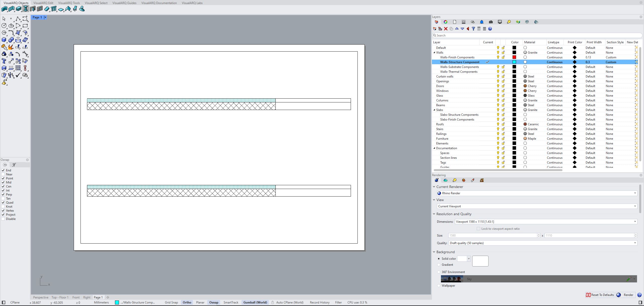
So far if i recall correct, the suggested workaround from Mcneel has been to use a custom Linetype in section style, but cannot find the relevant thread right now.
thank you
Best
alexandros
Ahh, so yes, this is not actually a bug. Its a confusing thing we did in v8 that we don’t do anywhere else and changed in v9 because.. well.. yeah we learned it was confusing.
Width Scale is for Display only. Its the same as when you go into the display mode settings and select how thick to draw Surface Edges. It doesn’t affect Print and is only for Display. That’s why it gets crushed by PrintDisplay or Printing. For v9 Width Scale is now a Display Mode setting and Print Width is now the configurable item. We’ve also tried to show you where the print width is coming from and what it will currently be. In the image below itll be the current layer which is using 0.5 mm.


The Display Width is now a per Display Mode setting under Display Modes > Mode (“Shaded”) > Objects > Clipping Plane > Edge Thickness Scale

In v8 the riddle is harder to solve but not to bad once you know how its plumbed.
In the example below the boundary linetype is By Layer (which is the Default layer) and so the print width comes from the Default layers print width. In this case 0.5. and Width Scale is literally just for the display modes, not printing.

let me know if that helps or not.
I reported it as bug since i thought it has to do with this track. But there i totally missed it is display only.
I understand what happens. Rhino 9 seems to have it all as it should.
In Rhino 8 what i am after is impossible, unless i am missing something.
As shown in the previous screenshots and per you description, whatever Print width i set in layers is applied in both cut and projected geometry when printing, which is not compatible with common drafting rules, where sections usually get thicker print width compared to their projections.
Yes you have been helpful,
thank you,
alexandros.
Another addition to v9 is a section boundary linetype can now be an existing linetype in the document. Eg “Dashed” where in v8 its just By Layer or Custom.

However, to v8’s point (after the other bug fix you pointed out). If instead of using By Layer for the linetype on the section style. You could use Custom and assign a custom linetype to the boundary with its own print width value. I would use MM for the Width on the custom linetype and it should be printed at that value.

Let me know if that helps improve the issue.
Yes Rhino 9 options, great and flexible. One could also consider having the option to select Layers. For example for Hatches an option to select a Layer from the Layers list, which has everything regarding the hatch like print width and color, display width and color etc.
In Rhino 8 Somehow i cannot get it to work. I apply custom Linetype set it as in your screenshot, everything gets the same print width.

This is because clippings happen through VisualArq levels and not a Rhino clipping plane.
I added a Rhino clipping plane and enabled it for Layout and top view.
Layer Section Style Boundary_Custom LInetype_RCPlane.3dm (4.7 MB)
Same result.
The left part is sectioned the right part not right?
How is this as advertised, when sectioned part is set to be 0.9mm and projected part 0.5 and they have the same width (i dont see a difference there)?
You need to move up the clipping plane, now it intesects with all the solids, while in order see what i am saying the right short solids need to be under the clipping plane, as projections. And in that case sectioned parts should print thicker than projection parts.
