Could someone help me figure out how to create a 2 part mold for this paraboloid shape that I’m looking to cast? I’m thinking RibbonOffset could do it but I’m having difficulty getting it to work for me.
I tried a different method - splitting it in half inside a box but it turned out hollow. I really just want a box that when you put it together there’s a negative of this paraboloid that I made…
Hello- please post your 3dm file, here if it can be public, or send to tech@mcneel.com if it must remain confidential, along with a lionk back to this topic in your comments. Isuspect RibbonOffset is overkill in this case but with your file, we’ll be able to tell more clearly.
Note you can paste jpegs or other images right in your post as well.
Hello- I made the plane at the base of the domed surface and BooleanSplit the box with that.(MergeAllCoplanarFaces on the box beforehand, to clean it up).
Then, BooleanDifference the object from each half.
So simple! That makes sense. Do you have any immediate ideas for making a draft? I’d like to keep the object as it is. Is that even possible? Or would I need to change the angle of the vertical walls so that they do draft a little bit?
I’m obviously not an expert in this but it would seem like you could do it by molding some excess material that later gets ground off or something. To give you a little more context - this 2 part mold will be made of laminated plywood sheets that get CNC routed and then injection molded with a very fine concrete mixture.
Yeah I might need to add a few degrees of draft. I was thinking I could keep the vertical walls and just grind or chop off a part of the molded part that would have the draft, but it’s probably most straightforward just to add in a few degrees of draft to the actual part, like Kyle just suggested. In an ideal world the walls would be vertical
Hello- I’d add the draft in this case, when making the object - you can revolve either combination of curves here, for example -
to get draft one way or the other. Of course which you choose will determine where the parting plane goes - at the base of the dome or the base of the skirt.
I think I just did it. I made a curve on one of the quadrants and then revolve it around the center of the convex surface of the paraboloid so that the concave surface stays the same. Can you double check my work to see if I did this correctly? I put the paraboloid with the draft in a new layer named Paraboloid with draft
Oh and then I used the trim command to delete the excess material. I did that in the front view and it still seemed to trim away the entire circumference…
(Also, my initial splitting of the box to make the mold halves, way up there ^^, was not quite right and neefds a bit more fiddling to be correct, when you get the part made as you like it)
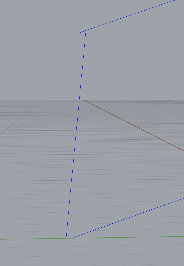
That makes sense. I’m curious how you did this though. What is the command did you used to make the line that the couple curves are aligned to? I did it with a normal line but I think you did something different. Also, when I adjust the vertical wall to a defined angle, not just freehand a new line and trim it, the line just floats like this (see image). Which command links it back up with the other curve? I realize this is super nitpicking but I’m just trying to replicate what you did and not change any of the other dimensions except for the wall angle slightly.
I could also just extend the wall line and then trim it on the top and bottom but I really want to know how to connect two lines together like what I was trying to do a second ago. None of the align commands are doing it.
Just figured out how to attach the line! I was trying to connect the two lines at the endpoints but then realized that it only snaps to the place where the mouse is, and that you must trim off the excess.
I still have no idea which command you used to create that guide line - it seems like it would be a guide but then I can’t select it in any way. I’m just really curious how you made that.
Also which aspect of the mold halves is not correct that you made? Just that the two halves aren’t exactly half? I was going to do it in a very similar way so I just want to make sure I’m not messing it up. I would definitely fiddle with the location of the splitting plane but other than that I don’t know what you’re referring to.