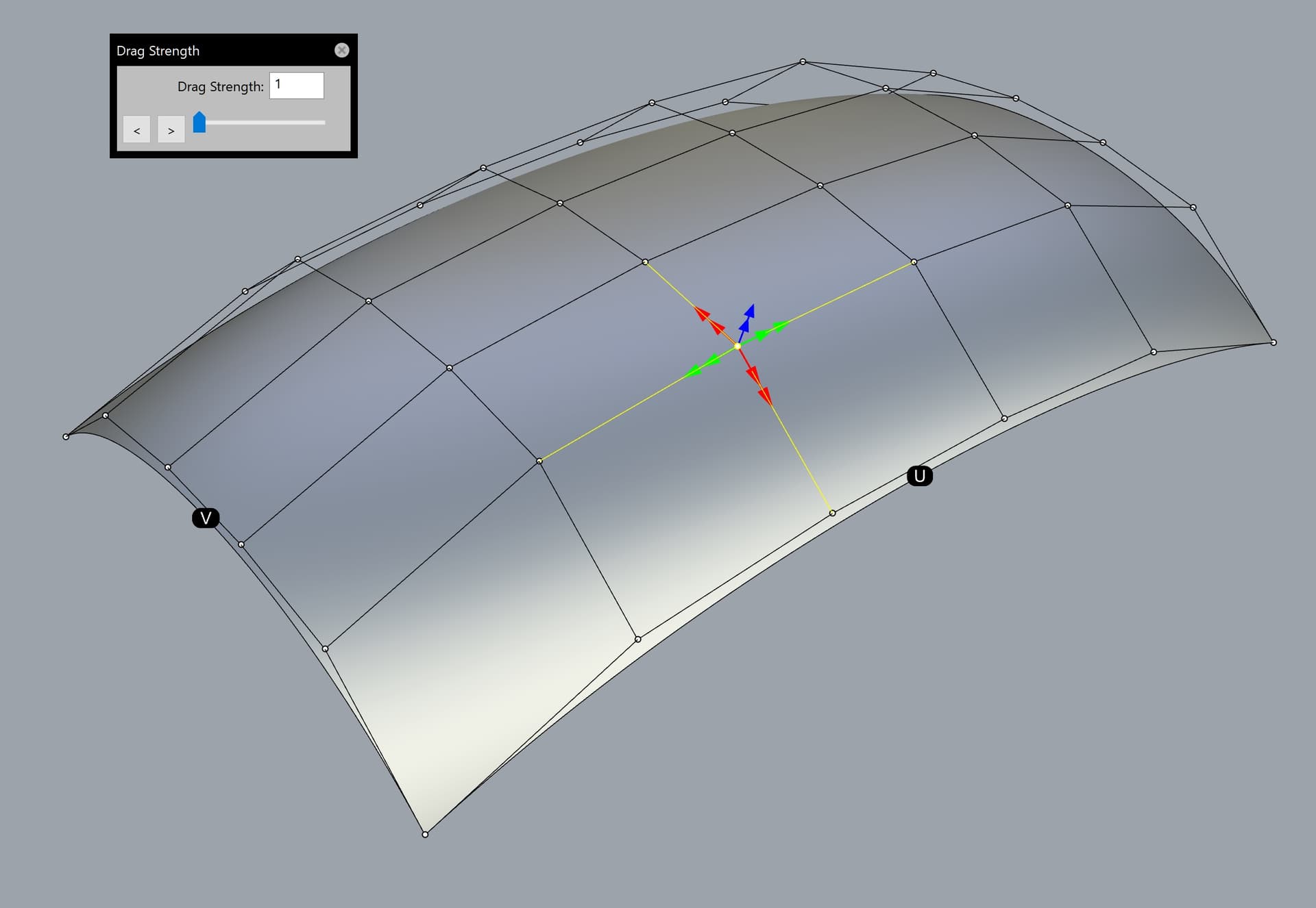
Attached here is a Rhino 7 3dm scene consisting a single surface with a proposal for a dedicated “CP Gumball” (control point Gumball) for convenient control point manipulation. You will notice that the arrows are colour-coded based on the U and V colours, and oriented along the control polygon of the selected surface control point. There is also an additional blue handle for moving along the normal direction. The idea is that when the CP Gumbal is active, Rhino’s current default Gumball should be deactivated.
CP Gumball.3dm (230.2 KB)
This is based on the “Super Gumball” idea proposed in my earlier posts in this topic.
Here are some more details about the CP Gumball:
-
When the CP Gumball is active, moving the selected control point will be free in any direction along the imaginary control polygon (4 flat planes based on the respective couple of control polygon vectors). Alternatively, the control point could be moved along the common average plane based on all 4 vectors of the control polygon surrounding the former.
-
If two or more control points are selected simultaneously, dragging any of them will move all control points simultaneously along their respective control polygon.
-
There are two arrow handles in any of the 5 directions. Dragging any of the inner handles will be at normal speed along the corresponding control polygon vector.
-
Dragging any of the outer arrow handles will act as a “Drag strength handle” automatically set to 5 for the current Rhino session. Note that when the “CP Gumball” is being activated, the Drag strength’s pop-up window should open automatically and be set to 5 (as mentioned above). The user could change that value afterwards. The default value could be customized from the Rhino options, in case that the user prefers any other value as a default instead of 5. Having dedicated “Drag strength” handles next to the normal speed handles will significantly improve the workflow of the users by saving time and reducing the mouse clicks.
-
“Drag strength” must be upgraded to allow entering a value lower than 1 (such like 0,1 or even 0,01), because the current implementation is too limited in that regard. Take for example the “MoveUVN” tool which has a dedicated button for up to 0,001 units, but clicking on the tiny “down arrow” against “Scale” could further reach even stricter values such like 0,0001 or 1E-14 units.
-
The user must be able to customize the size of the arrow handles (similar to the customization of the default Gumball), as well as whether the triangle arrows will include bars starting from the control point, or not (just a tiny triangle handle with no bar).
-
There must be two dots along the middle of the positive edge of any surface with visible control points, named “U” and “V”. This is self-explanatory. They could be either black with a white letter inside, or coloured in red and green for a greater visual distinction (or any other colour combination set by the user). Furthermore, these dots could be shown upon running certain commands related to UV direction, such like “Extract isocurve”, “Dir”, “Rebuild”, “Rebuild UV” etc.