I’ve created some files using Rhino OSX and now that I have acquired my CNC 3 axis mill, I’ve started using those files for test practice runs. I purchased Rhino for Windows and so I’m working in the Windows version, but the files were originally drawn in Mac. I have purchased Madcam plugin for Rhino so I’m using that to generate the toolpaths.
I am getting some glitches in the cutting - occasional high and low ridges in finishing cuts on the 3D mould surface. I know there must be a hundred possible causes but I wondered if there are any potential bugs with using Mac created files to generate 3D toolpaths?
I draw everything in Mac Rhino and then export as an STL to Deskproto (on a PC) in order to generate G-code for my CNC mill. For what it’s worth, I’ve never experienced any of the errors with the resulting file as you state. Do you have similar problems with tool paths completely generated within PC’s?
There shouldn’t be. The geometry engine between the two is the same, so you should get the same results doing the same operations with the same parameters on both.
For what its worth I’ve done about a half dozen very complex organic forms using OSX Rhino and then generated toolpaths in RhinoCAM under a VMFusion Windows environment and never had a problem. So you had me at 3D wing shape, can I ask what you’re making?
Haha, thanks Dave! I’m a model RC sailplane flyer … slope soaring and dynamic soaring. What’s your particular passion??
This one is a stabilizer for a homebrew dynamic soaring plane I’m working on called the Angry Bird (a seriously modified Sting F3F with an Xtail, revised boom angle, and very beefy joiner/ ballast boxes. I’ll attach a pic of the mould I cut yesterday with the lines on it.
My interests while largely theoretical at the moment are a bit grander/stupid. I’ve got a couple homebuilts that I’ve worked on extensively but didn’t build from scratch and have the bug to do a design of my own. If you’re familiar with Burt Rutan I have the plans prototype Rutan Defiant and am partnered with a buddy of mine in two seat amphibian called a Volmer. My CNC is primarily work dedicated for my day job in consumer products but its big enough to make cowls, control surfaces, and wheel pants if you split things a bit. I’m actually planning on doing a 20% scale model similar to your size stuff first so your site was of huge interest.
If you post an .nc file of your mold I’ll take a look at it in my copy of Mach3 or one of the simulation modules I have access to and see if your gcode is the problem. Also take at look at this link:
The owner of the site is a very clever guy and huge Rhino user. Besides after your two links cost me the better part of 2 hours its the least I can do.
Dave,
thanks very much. Wow, you’re into some impressive stuff!
Mick, a guy from Western Australia has become a bit of an adviser and although he’s not a Rhino or Madcam guy, he’s helped with a few things including getting me to send him the code for that cut … he used a thing called MCU and did find some problems. I’m away from home and … oh, bingo … thought I didn’t have it but I found it … so I’ll attach it in case you want to have a look too. I have no idea what to do about these problems however at the moment. Since postprocessing that one, I did find that my “absolute tolerances” in Rhino were set to 0.01, so I changed that to .001 and the relative to .1% … I’m not sure if that will have an effect? I did originally set the other render mesh and model settings as per the Madcam instructions, and have tightened them up a bit further since.
Hey I have actually seen that Stretchalon thread before - it sounds brilliant and I would do it for a prototype thing. Probably a bit sloppy for the high end moulded stuff I’m aiming to do! But a superb idea.
I’m still very much clueless with Madcam. Not just learning what the different options and settings can do,but also how the system copes with editing/ changing things. Can you tell me, if you have created a number of toolpaths (say facing, roughing, z level then planar) and you decide that you want to edit the roughing path - maybe a bigger stepover or a bigger cutter, how do you know if the subsequent toolpaths have adjusted to the different amount of material left? (or what if you actually delete a whole toolpath?) Do you need to go back and recalculate them? Does having the other toolpaths hidden or locked make any difference?
If I have changed to a different cutter and recalculated a path, it doesn’t change the name of the layer and still has the old name, so I have trouble working out what cutter it is now set to (unless I postprocess it and look at the report).
Also if I am using different regions for different parts such as a plane for facing, the main wing shape for the main work, and then a trailing edge trench … I have to reselect the model at times and/or the region curves and I really don’t know how this is affecting other things … if I go to recalculate an earlier path it tells me that it can’t find the model …
I don’t think I know enough to ask good questions!
Aaargh!
Surely there must be some good info somewhere about all this but I’ve looked at the tutorials and threads and haven’t found anything that really helps me to understand it.
Didn’t see any files attached here or at the McNeel site so you might have to send it again.
The tolerance thing will definitely cause you problems and I’ve dealt with some similar issues doing really fine engraving on parts in the 3" inch size range.
I’m not familiar with Madcam but none of the other CAM packages I’ve worked with are really aware of the effects of the other operations. The exception to that being if you edit a tool that gets used in other operations and then regenerate the tool paths for the other ops. For instance on your wing mold in RhinoCAM, would be a horizontal roughing operation to clear a bulk of the material from the pocket, followed by a horizontal finishing operation with a very fine step over. The finishing operation wouldn’t really care what the step over on the roughing operation was and vise versa. The simulation module in RhinoCAM would show the effects of any changes in step over or finishing stock that was left by the roughing operation but that data doesn’t get used in the generation of the second finishing operation. Probably clear as mud.
Anyway, shoot me a copy of your file and I’ll take a look, a defect the size of what’s in your picture should be pretty easy to pick out. At least then you’ll know if you’ve got a software glitch or something wrong with the machine control.
There are actually quite a few programs that do this, particularly for re-machining operations. Some programs do re-machining based on the user manually entering the previous tool size - and are thus semi-independent of the previous operation - but others are completely linked to the previous operation and will either update automatically when you change the previous tool size, or tell you to manually update.
Dave, I did attach the file via email but it mustn’t work unless logged into the forum? Anyway here it is again. Thanks. 45 Planar_Ball end 3.txt (5.1 MB)
Ah, well thanks - I thought that for the next toolpath the program calculated the material left, when calculating the subsequent one.
I understand that “Pencilling” does that??
I looked at remachining but so far don’t understand it so I’ve kept clear!
I spent some time yesterday experimenting and ascertained various things, but still have questions - but they are well off topic and I should put them on the Madcam forum!
Newbie guys like me are a nuisance and a frustration to you experienced guys … sorry!
Mitch’s comment above and your thoughts regarding pencilling operations are entirely correct. Re-machining type operations definitely take into account the previous operations either automatically or via a required parameter input. Bad assumption on my part regarding how much CAM software you have. Re-maching operations tend to be at the higher end of the CAM feature spectrum. Currently in RhinoCAM neither the basic or expert versions include these operations and you’re up at the pro version before they’re included. My background is model shop and prototype work where its basic 3 axis machining and sandpaper. I’ve run the native CAM’s on ProE, SDRC, and UG in addition to the RhinoCAM that I’m running now and none of the standard machining packages had re-machining operations when I was using them. If you’ve got a package with re-machining you’ve got a whole lot of CAM software and once you get the hang of things should be able to make some spectacular molds.
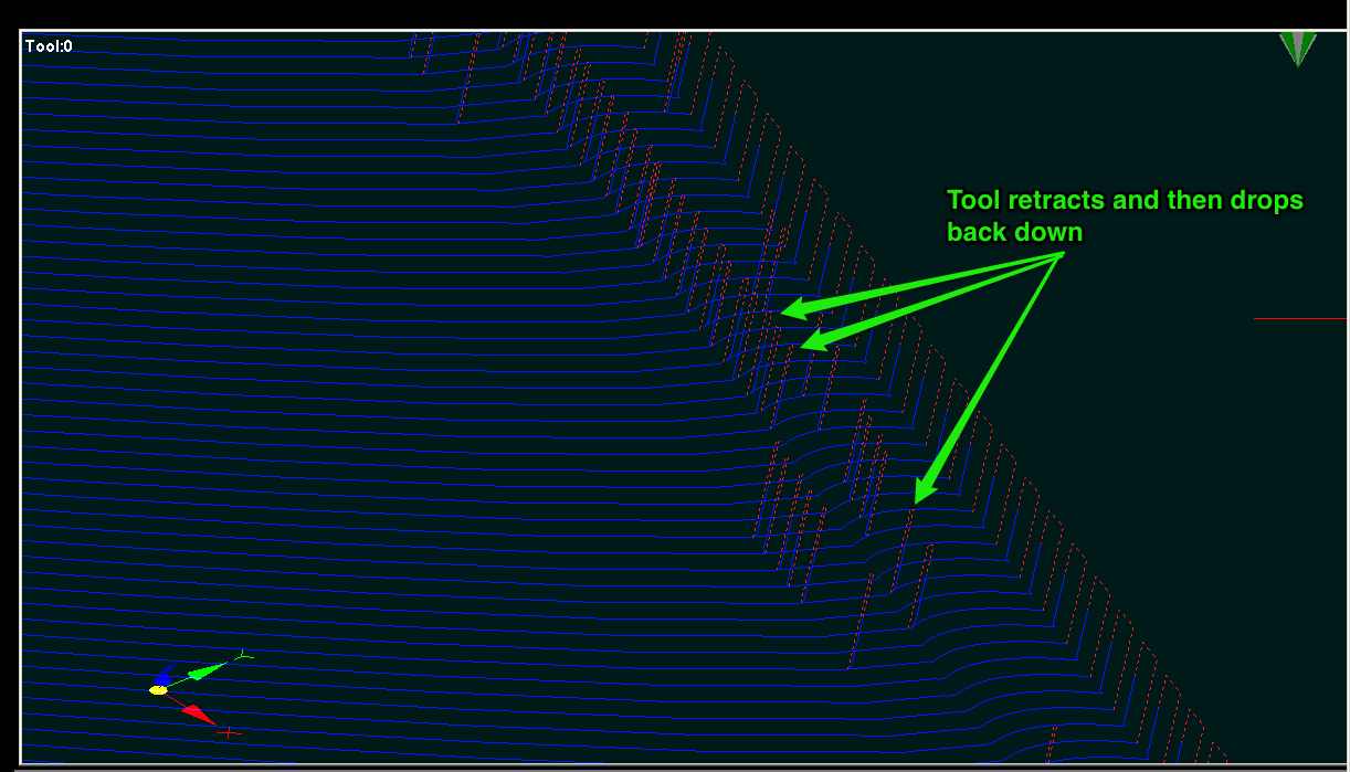
I did take a look at your file and while I can’t see anything in the code that would create the 45 degree grooves I did notice a whole mess of weird tool retracts on the leading edge of your part.
I doesn’t look like any of these would gouge the part but its certainly going to slow things down and there doesn’t appear to be any reason for this to have occurred. I pulled this into Mach3 to look at it so if you’re using a different machine controller its possible your milage may vary if you’re using something else.
Don’t worry about just starting out, everybody does at some point, and if you play your cards right, you’re always just starting out and learn something new every day. Case in point being it might be time to go look at the UG machining again.
Dave, thanks very much. Yes, you’re right, that was a big problem with that cut and it did leave some unwanted marks on the LE. I’ve recreated the Rhino model file to get rid of some bugs and have been practising further to see how to eliminate the unwanted movements, which I’ve been able to do by using a Z level finish first, then a planar finish, and certain options.
Rather than explaining it here, you can read where I’ve written all my questions on the Madcam forum: HERE
(brace yourself, it’s a long read!)
I have the education license for MadCAM which does have all the full features, which is great. I will have to look at remachining sometime but I need to get lots of practice on the basics first!
What do you mean about looking at UG machining again? Did you mean you or me to look at it?? It took me a bit of googling to work out what it is. Surprised to find it works on OSX!
I thought I should update and close this off by saying that I got some great help from Svenakala about using Madcam, tweaked the settings and have made my first excellent set of moulds from that shape. Once the tolerances were sorted out I had problems with rounding of the leading edge corner on the finishing cuts which was due to the constant velocity behaviour of Mach3, and once I’d tweaked those settings I got a fabulous result. Thanks again for the advice.