Trying this fancy new alternative to shrink in Rhino 7 for the first time, and not only do I get instant fail, the surface I’m trying to refit also looks funky, regardless of custom mesh setting:
(Btw, the above result is after a ShrinkTrimmedSurface, as the original untrimmed surface was a perfect donut… doesn’t make any difference for RefitTrim, and both before and after, the left edge is impossible to select for the command.)
Yes that command should be used with caution. It allows trim curves to fall off of the underlying surface, which ShrinkTrimmedSrf does not. At any rate, refitting the edge works in somewhat limited cases - the trim must traverse the surface completely, not the case here.
Definitly, many complicated corner blends were almost impossible to do without this feature. Great work. If @davidcockey wouldn’t have told I would have completly missed that feature.
The area to be refitted has to be a “rectangle” with four sides. In some instances it works when some of the sides have zero length.
It is important to understand that RefitTrim will usually alter the shape of the surface, and that the new untrimmed edge will generally not exactly match the previous trimmed edge.
In the scenarios I would use this feature, I usually want to reach tangent edges in all directions. This makes sure that any sort of blending has perfect conditions to match. This is why I usually create the trimming shapes with a single span of degree 3 (or order of 4) at maximum. The planes in the example where created by a blend curve with 3 controlpoints, tan to one end and pos to the other end. Because I just needed tangency edges to the top fillet.
If the cutting shape is of lower order as the shape to refit, it is almost impossible not to perfectly alter the new boundary!
However something you really have to be aware, is that a refitted surface might also loose its continuity to its neighbouring surfaces! Moving cps in iso direction also affects the continuity to a certain extend.So, I would always check if (in this case G2 fillets) are still close to G2 after the refit. But usually, when low curvatures are involved (like in my example), this impact is really low.
A coworker just asked me if Rhino could help with a ship hull that has a lot of trimmed surfaces that needs to be translated from NX to MaxSurf (which doesn’t understand trimmed surfaces).
Again, I so feel the pain right now that RefitTrim can’t deal with surfaces which are trimmed on more than one side in one go…
All of the trimmed surface edges must be merged in order for the “Refit trim” tool to work. Also, only one of the surface edges must be trimmed at a time. This is a big limitation, but if you can understand the basic principle of the tool, it could be quite useful in certain situations.
One thing that could help to at least some degree is to add some warning message in the Command line or in a pop-up window that will give a feedback about the error that caused the inability to refit/trim the surface. Currently, there is no warning and Rhino simply refuses to register any interaction between the mouse pointer and the trimmed edge.
…and I just have to ask, is that improvement that RefitTrim can now handle a trim curve (or multiple trim curves) which don’t cut across the entire underlying surface?
It’s been two years and I’ve still not come across a single practical use case for this tool, since in exactly zero real world models (which come across my desk) are surfaces ever perfectly and cleanly trimmed across one side only.
I actually had ONE successful use of “RefitTrim” since Rhino 7 released on the market at the end of 2020. That’s about 2,5 years of full-time working on models in Rhino. All of my other attempts to use it for accurate conversion ended with obvious failures.
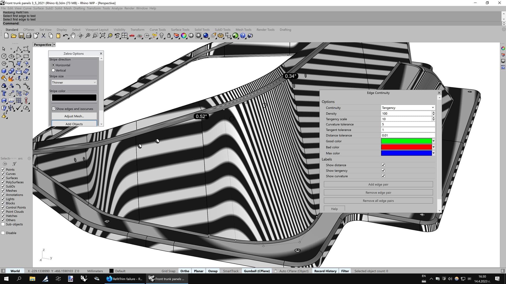
I played a bit with the same tool on Rhino 8 WIP and it performs better, but still produces some deviations that should not be there. For example, applying “RefitTrim” to a straight blend between one vertical and one horizontal surfaces resulted into deviation up to 0,4 degrees, which is weird, because the only thing that the tool had to do is to slide the control points of the converted surface sideways and maintain the G2 continuity. The good news is that “RefitTrim” is better in Rhino 8 WIP, the bad news is that it will forever remain almost unusable in Rhino 7 (unless multiple “Match surface” operations are added to fix the huge deviations at the other 3 ends of the surface).
I just made another test of “RefitTrim” in Rhino 8 WIP and must say that it still fails to do the job properly on the same model where Rhino 7’s “RefitTrim” also failed. Basically same behaviour on the same 3d model, with a deviation up to 0,52 degrees. This is way too much of a deviation for a simple blend surface created between two planar surfaces. Looks like those claimed improvements of “RefitTrim” in Rhino 8 WIP are limited to rare scenarios.
I find it works really quite well in the WIP. In fact it’s the only reason I use the WIP at the moment.
I model nearly always in single span and when the refit drops out of tolerance I increase the degree. Only in a rare few cases does it fail and I have to increase degree outside of the command.
Rhino 8 WIP’s improved “RefitTrim” resulted in 0,34 degrees deviation on the right edge, while Rhino 7 did it a bit worse at 0,37 degrees. Both are unusable. Manually sliding those control points along the vertical direction of the control polygon with “MoveUVN” let me maintain perfect G2 continuity.
@bobby, I am not sure if that is even possible without any deviation, for that I need to see the geometry. In some cases there will be no deviations, in other cases you will need to match the surface after the refit. Can you post just the three surfaces in question?