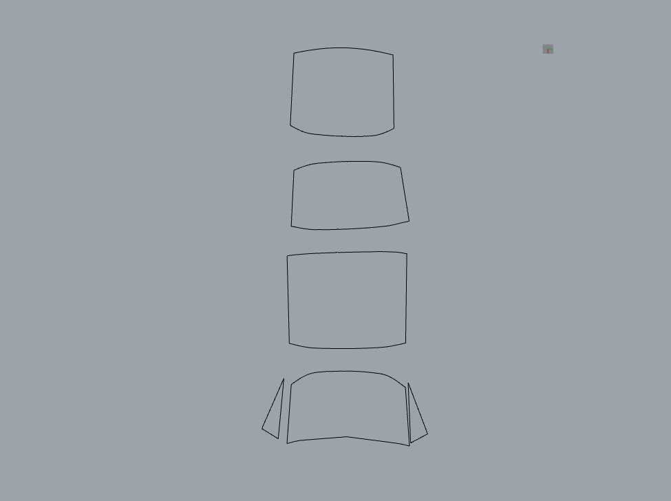
Hi All, I am very new to rhino and I am using it to create and design covers in the marine industry, Paired with measurements taken from a 3d measuring device. To achieve the results I am looking for I have only had to learn the very basics in rhino, the main being the loft function and unrolling surfaces into 2d so they can be cut by a laser cutter, I have uploaded some pictures below showing some of the work and success I have had so far, however, I am still having problems when unrolling surfaced to 2d, sometimes they come out deformed, and sometimes they won’t unroll at all. If anyone could give me any advice I would really appreciate it
Hi Kallum - hard to say without the surface. Without knowing anything at all about how fabric behaves or how allowances should be made, I made an approximation, does this look viable?
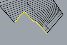
Hi there, Thanks for your response, Fabric is very forgiving when it comes to allowances, we work to a 10mm tolerance, I have uploaded a picture, everything highlighted in red is perfect, however, it needs to follow that line in blue, I don’t know the ins and outs of the loft function but I am guessing its something to do with it being an odd shape ?
@Kallum_Duffy The main point being that I extended the edge lines to meet across that cut off corner and made my
surface from those, then pulled the complex corner trim to the surface and unrolled it with the surface - could use it to trim before unrolling as well.
Hi Pascal, Thank you very much! you made that look easy I will use that technique in future projects if I am having the same issue, I have recreated the same thing on the other panel (Left Side) however I am confused on how to pull that line into the surface, I have uploaded some screenshots and the project if you could care to take a look, As it would be brilliant to completely understand the process you took to get this end result as the panel you edited was perfect. Right Side Panel.3dm (27.4 KB)
Here’s what I did, I think though not strictly the best way to get developable surfaces (DevLoft might be more accurate but more painful) I think in this context you may be able to get away with it
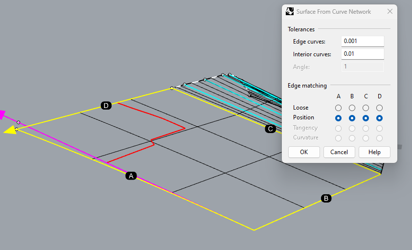
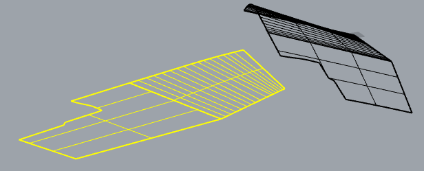
Make two surfaces, split at the kink in the outline curves:
On the more curved side, I connected the end points of the curve fragments to ‘logical’ locations on the line opposite:
in order to persuade NetworkSrf to align itself nicely or nicely enough
On the flatter side, I extended the lines that intersect that complex trim on the corner:
As is, they do not meet. The ClosestPt command with the Object option will mark where they come closest. (points in my image). Then you can add a new line (cyan) to approximate that edge, or add a new curve that drops down there to approximate: