I am working on a 3d model that I can machine on my CNC. I am constantly referring to Sky Greenawalt’s “Primary Surfacing” videos and luckily it makes more sense every time I re watch them
On my guitars I like to do the surface the same on both the treble and bass sides, upper and lower bouts, so the cutaway portion near the neck, if view from the neck end, would kind of look like a baleen whale’s teeth. some builders carve the cutaway area surface to come down to meet the profile plane, so the binding width doesn’t change in the cutaway. If you are a guitar builder you probably know what I’m talking about. So, I could do a half of the profile, mirror it, surface it, then trim out the cutaway area, as I do when manually carving these. But I have heard it its not a good idea to trim.
I’m not a guitar maker nor English mother tongue so I don’t understood your question.
Here in the forum we have many, very good, guitar makers.
From what I understood your level of knowledge is, for now, pretty basics so my best suggestion is not to wait and dig into the solution you think is the right.
You may find the result not completely correct but next time you will have a starting knowledge.
I know it sound like wasting time… I wasted this way my last 20 years
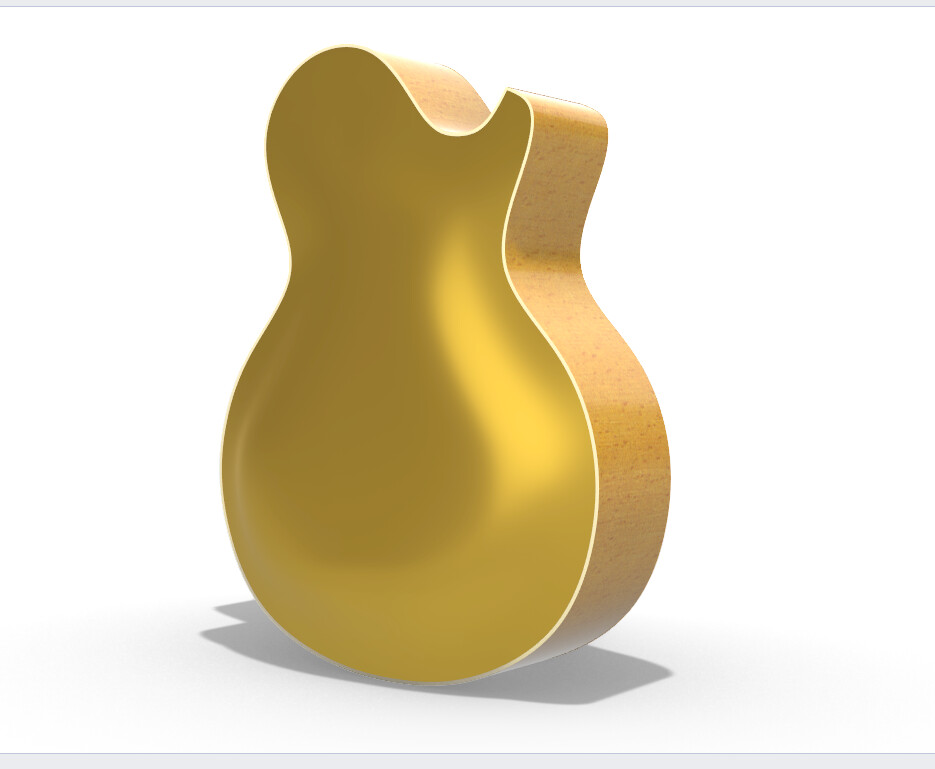
This is a LP deluxe. The binding width changes as the bottom edge stays co planar and does not follow the rise and fall of the top.
If I understand correctly you want to model a carved arched top so the binding can stay the same width like a standard, but also has the bottom edge of the binding coplanar like a deluxe.This requires the treble top surface to dip down towards the back in the cutaway area so it is not the same as the bass top surface. I think your question is how to model this top surface.
Yes, modeling the top , and like the Deluxe. Modeling the neck is for another day - lol. I’m very new at 3d modeling, but not very new at shaping tops by hand - hollow body archtops. The inside carve is another story.
Very nice! Being a noob, and such, my problem right now is how many surfaces, and where? I am trying to constrain myself to single span curves and have minimum CV’s. Still trying to get my head around what isocurves are, along with tons of other things.
If you want the appearance of a LP deluxe in the cutaway you can model symmetrically across the centerline and chop out the cutaway with Wirecut. This would be a typical treatment of this area for a hollow body arch top. There will be some softening and blending needed as you go around the horn. Pascal’s basic layout of surfaces is really excellent,
Trimming tools can be very useful-don’t be afraid to use them. You are fortunate in that you approach these questions with the background of a craftsman. So when in doubt you can follow a similar workflow but with digital tools.
Fewer control points are good, but not at the expense of inability to achieve the desired shape or matching between surfaces.
There are valid reasons to use single span curves and surfaces in many situations, but there are also situations where a multi-span curves and surfaces are desirable.
The large surface in Pascal’s example provides automatic curvature continuity between spans (assuming a degree 3 surface), and a minimum number of control points compared to splitting it into multiple single span surfaces. If multiple single span surfaces are used then curvature continuity (if desired) has be achieved by manipulating control points, and the total number of control points will be significantly larger.
Would you mind explaining the work flow you used, especially in the cutaway areas, or marking the subsurfaces on your pic? And which surfacing commands to avoid? I tried patch, but it got messy. I was thinking of creating small surfaces and joining them. I feel like the less control points the better, yeah?
That’s great - it’s making more sense now…
Did you layout the “horseshoe” shape at highest z, then layout a profile at z=0, and then connect the 2 with degree 4 curves going along the “horseshoe”, or do a sweep2 ?
This is helpful
Here is what I’m trying to model for posting to my CNC, mostly to do the neck carving, and to carve the top and back plate inside and outside arching. A lot of stuff can be 2 1/2D, which is duck soup in this case
Kyle - I just figured out the rest of your reply - awesome. I definitely will look at the 3d and see how to morph it into a set neck with angled headstock.
An inherent drawback to SubD modeling of surfaces with sharp edges is on display in Kyle/s guitar. Curvature goes to zero normal to sharp edges. This is unfortunately inherent in (the McNeel implementation) of SubD modeling. For many purposes it may be okay, but it can be obvious.