I have a relative simple point cloud (300 points) of a building site. The purpose of this model is to verify the average height of the building site (accomplished) and to create a mesh to verify the difference in level in a visual way and to verfiy the volume of excavation. I am not able to create a mesh of these 3D points can anaybody help me with this.Kavelinmeting.gh (27.7 KB)
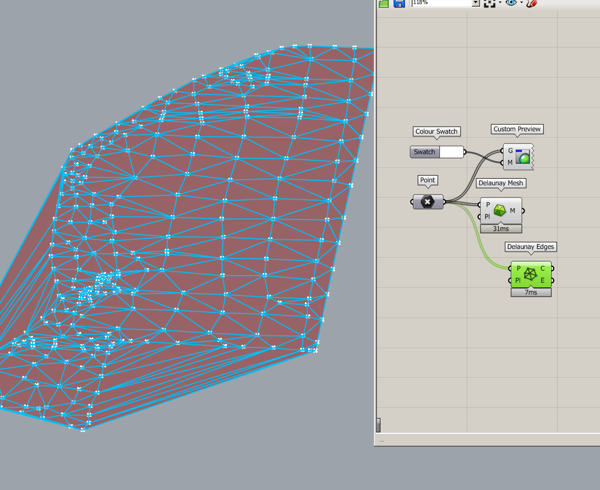
The Delaunay surface has distorted areas. As you can see in this image the shape of the building site is different. Blue are the outer lines of the building site.
If Delauney can deliver the goods (case: co-planar or almost co-planar point collections) you must discard the faces that are outside the boundary. There’s various ways to do that (by projecting all your points plus the boundary (if they are not co-planar) to a plane and then use various filters for excluding the unwanded faces) . That said I could provide an example but using solely code (C#).
Another (slow) approach is to patch the points.That yields a BrepFace and then you can use MeshMachine for a far more good looking mesh.
So basically the points are mesuared with a GPS system (other company) the 3D cloud (current height of the building site/soil) will be excavated in order to acchieve a planar building site. So the volume compared to a particular plane level is usefull to know how much ground needs to be excavated.
So Delauney delivers the goods but I have no boundary in Grasshopper yet but would like to have it.
If you could provide a C# code or another solution I would be really really helped! Using native components is another possibility.
No boundary eh? This points us to a concave hull thingy (nothing to do with a convex one). The bad news are that my C# stuff that does that is strictly internal.
It is like the ConcaceHull ACM MYS .pdf document.
Though is could bake the points in Rhino and then manually (costs only a few minutes) construct the outer boudary line (indated in blue in the image above that goes trough the outer points) if that helps.
If its a one off that’s what i would do. Put the project on, trace the boundary. Reference into GH, Cull anything outer. 5 Mins. If this is a steady workflow Peter’s solutions would be optimal.
Truth is that our friend Rickson did 100% the right thing … but is the right thing the right thing? (LOL)
In plain English: if patch cuts the mustard (Karma, what else?) AND deviation is minimal (non existend in fact) AND your points yield an ugly Del mesh (uneven density etc etc) … why not doing business with a nurbs solid? (Or - plan B - a BrepFace > MeshMachine> WOW mesh > …). That said I hate terrains as meshes in AEC like my sins.
From a mathematical point of view I agree that the previous Del mesh is rather poor due to the angels and deviations etc. Though for this purpose (excavation) an accuracy of ± 5 % is acceptable. Your script provides an even better result. Anyway I encounter problems using your script if the X and Y coordinates of the “point cloud” is far from the 0,0 point in Rhino. We use coordinates according RD (0,0 is Paris France). Furthermore would it be possible to include a Z-axis variable. I mean at the end you make a Solid (trimmedPatched) with a certain Z height. Is it possible to include a numerical variable to calculate e.g. an excavation of 5 meters? In principle the script i.e. MeshMachine itself is awesome!
Well … other than tol matters (critical most notably in meshes) related with points from Mars (and beyond)… I confess that I have moved your stuff because my NVidia Quadro 5000 used displays nothing (OEM points). This is probably some OpenGL issue (and No … I don’t change the driver [CATIA/NX works fine so why bother?]).
With regard that C# I’ll fix various stupid things ASAP (Is a very privitive thingy written in one go with no testing etc etc).
By 5 meters you mean that that value is subtracted from the min point Z, correct? (or the average? or the max?) Anyway I’ll add boundary Z translation as well and far more effective ways to do this (and that).
With regard excavations: well … in fact you can’t do them (general case) because the R polyline offset is crap (and taper in general has issues as well : Brep.CreateFromTaperedExtrude). And why you need an offset (outwards) + taper? Because of the free space and the fact that the exc walls are inclined (in real-life they have a slope - related with the soil stability unless other ways are used [mini piles, Gunite etc etc]). That said I can’t provide the proper poly offset thingy (concave polyline, any shape and the likes) because is internal.
So we need:
Translate (at exc depth) and then offset the boundary in order to provide space for foundation offset/framework/drainage pipes and the likes (1m outwards is OK in most of cases). Don’t forget to protect the thermal insulation (use AKZO etc etc)
Then we need to taper the poly (as Curve). A straight extrusion is not real-life (unless the soil is rock). But if the soil is unstable the taper angle is big > Armageddon.
That said excavation in any imaginable terrain is not a R/GH thingy (you’ll need a proper solid modeller for that one - and a BIM driven app).
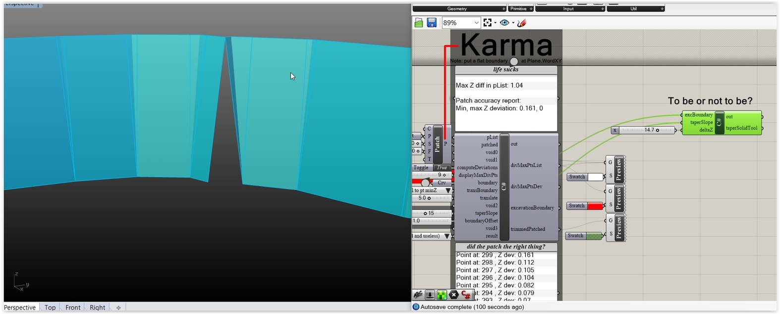
But for this boundary and with a minimum slope/depth … hope dies last (Karma: a must as well).
Found some minutes for some pre-ignition tests. Leaving aside the offset part of the story (bad news as usual) … taper does what is expected to do (chaos, that is: for this boundary and for side slopes > 5 degrees [ that is highly unrealistic] ).
I hear you: but you can write a Method and bridge the gap don’t you? Yes I can … up to a point (if the result is 100% bananas we need lot’s of lines of code > better learn CATIA).
Of course all that point to a non mesh solution (life sucks).
Assume excluding the taper part, that will make it a lot easier for your code. If it is a straight excavation I can simply add a mathmatical part to add the volume of the taper ( (Zvalue (height excavation) / tan (angle taper))* 1/2 Zvalue * curverlength = volume) this approximates the volume accurate enough.
Trigo based volume approximation: no no (what if the terrain is not - almost - flat and/or has local min/max areas ?). Are we after the truth out there or what?
BTW: The only thing that could help right now is a proper Vodka overdose (and some cigars)
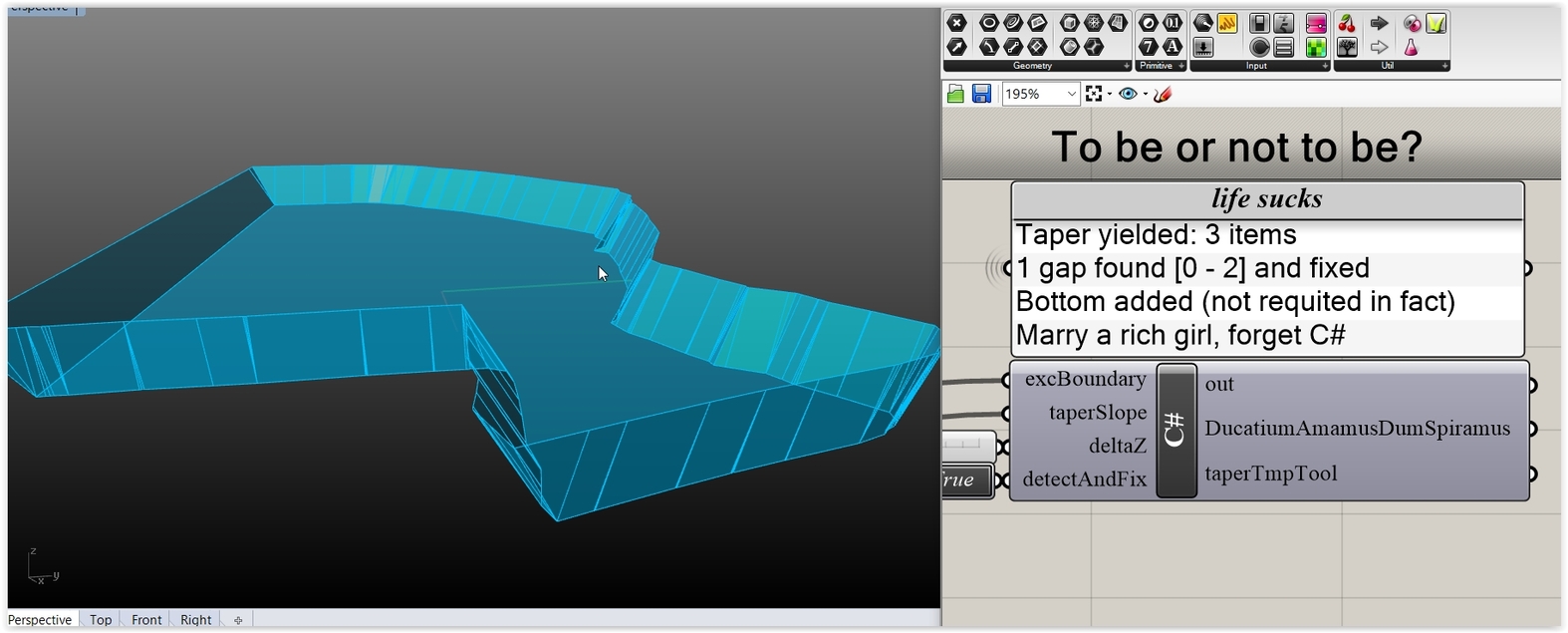
Adios taper (is so faulty that I should write lines until the end of time [and the Vodka]).
Other mysterious (and ominous) things are used: IF the offset works (the crap R offset, that is) then the excavation solid is done for any slope angle (in 1/50th of the time that taper needs). Due to these Methods the soil is painted black (what else?).
The rest are purely bureaucratic stuff (boring checks, stupid messages, mandatory Ducati Panigale promos etc etc).